Opel Frontera UBS. Manual - part 2553


  Index      Opel     Opel Frontera UBS - service repair manual 1998-2002 year


Search            


Content   ..  2551  2552  2553  2554   ..


Opel Frontera UBS. Manual - part 2553


AUTOMATIC TRANSMISSION (AW30-40LE)

7A–75

ON-VEHICLE SERVICE

 242RX00001

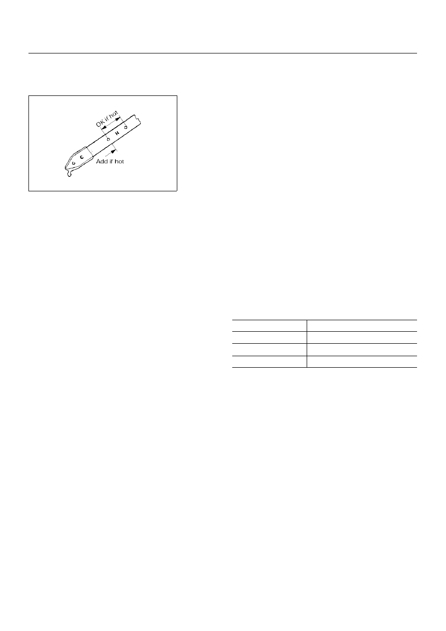
TRANSIMISSION FLUID LEVEL AND
CONDITION

Park vehicle on level ground and set parking brake.
With the engine idling, move the shift lever through all
positions from "P" to "L", then return to position "P".
Check to see If the level of fluid comes to "HOT" range
of about 80

°

C (176

°

F) on the dipstick gauge.

If the level of fluid is too low, replenish to bring it to
maximum level in "HOT" range.

Inspection of fluid condition
If the ATF is black or smells burnt, replace it.

ATF REPLACEMENT

NOTE:
Do not overfill.

1) Remove the drain plug from oil pan and drain the

fluid.

2) Reinstall the drain plug securely.

3) With the engine OFF, add new fluid through the filler

tube.

4) Start the engine and shift the selector into all

position from "P" through "L", and then shift into "P".

5) With the engine idling, check the fluid level. Add fluid

up to the "COLD" level on the dipstick.

6) The ATF level must be checked again for correct

level with the "HOT" level.

NOTE:
To prevent fluid leaks, the drain plug gasket must be
replaced each time this plug is removed.

Transmission

Drain and refill

5.2 L

Dry fill

8.7 L

Fluid

BESCO ATF III

7A–76

AUTOMATIC TRANSMISSION (AW30-40LE)

249RY00010

249RY00008

NEUTRAL START SWITCH INSPECTION

Inspection

With a circuit tester, make a continuity test on the neutral start
switch with the moving piece set in each position.


❍ 

Continuity

Removal

Preparation:

Disconnect negative (–) battery cable.

1. Remove rear sound cover.

2. Remove the rear side ATF cooler pipe from the

transmission elbow.

3. Disconnect neutral start switch connector.
4. Unstake the lock washer, and then remove the shaft nut.
5. Remove the neutral start switch.

Installation

To install, follow the removal steps in the reverse order, noting
the following points;

Adjustment

1) Loosen the neutral start switch bolt and set the shift

selector to the "N" range.

2) Align the groove and neutral basic line.

3) Hold in position and tighten the bolt.

Terminal 

Position

1

4

3

5

2

6

8

7

9

P

R

N

D

2

L

Torque

N·m (kg·cm/lb·in)

Nut

7 (70/61)

Bolt

13 (130/113)

AUTOMATIC TRANSMISSION (AW30-40LE)

7A–77

310RW020

F07RY00017

F07RY00018

BRAKE SIGNAL INSPECTION

Check that the brake light comes on when the brake pedal is
depressed.

VEHICLE SPEED SENSOR INSPECTION

1. Connect the Vehicle speed sensor connector terminal (1) to

the battery (+) terminal and terminal (2) to the battery (-)
terminal.

2. Connect a resistance of 1.3k ohm to 5k ohm (1.4W or

more) between terminals (1) and (3).

NOTE:  
Be extremely careful not to connect the battery (+) terminal
to the terminal (3)
This may damage the vehicle speed sensor.

3. Rotate the shaft of the vehicle speed sensor slowly and

measure the voltage at both ends with a digital tester.

Replace the sensor when the result of inspection is found
abnormal.

INPUT AND OUTPUT REVOLUTION
SENSOR INSPECTION

Use an ohmmeter to measure the resistance between 
terminals 1 and 2.

The voltage, with one rotation of shaft, fluctuates four 
times in the following range: 10 to 14V 

⇔ 

2V or less.

Standard resistance

560 – 680

 (20

°

C)

610 – 740

 (40

°

C)

7A–78

AUTOMATIC TRANSMISSION (AW30-40LE)

F07RY00019

225RY00001

220RY00001

244RX00001

PATTERN SELECT SWITCH INSPECTION

Inspect that there is continuity between each terminals.

OVERDRIVE OFF SWITCH INSPECTION

Inspect that there is continuity between terminals 2 and 4.

SOLENOID INSPECTION

1. Resistance check

• Using an ohmmeter, check the resistance between each

terminals (S1/S2/SL) and body.

• Using an ohmmeter, check the resistance between

terminals (STH) and (STHG).

 
NOTE:  
If the pressure contorl solenoid resistance is not within
specification, replace the valve body assembly.

2. Operation Check

Check the solenoid operation by blowing into an oil hole as
shown in the figure.

Solenoid S1 and S2 (Normal close type)

Solenoid S1, S2 and Lock-up 

solenoid resistance

11 - 15

Ω 

(20

°

C)

12 - 16 

Ω 

(40

°

C)

Pressure control solenoid 

resistance

5 - 5.6

Ω 

(20

°

C)

5.4 - 6.1 

Ω 

(40

°

C)

When battery terminal is 

disconnected

No air leaks

When battery terminal is 

connected

Air passes through


Content   ..  2551  2552  2553  2554   ..