Content .. 2536 2537 2538 2539 ..
Opel Frontera UBS. Manual - part 2538
AUTOMATIC TRANSMISSION (AW30-40LE)
7A–15
F07LV001
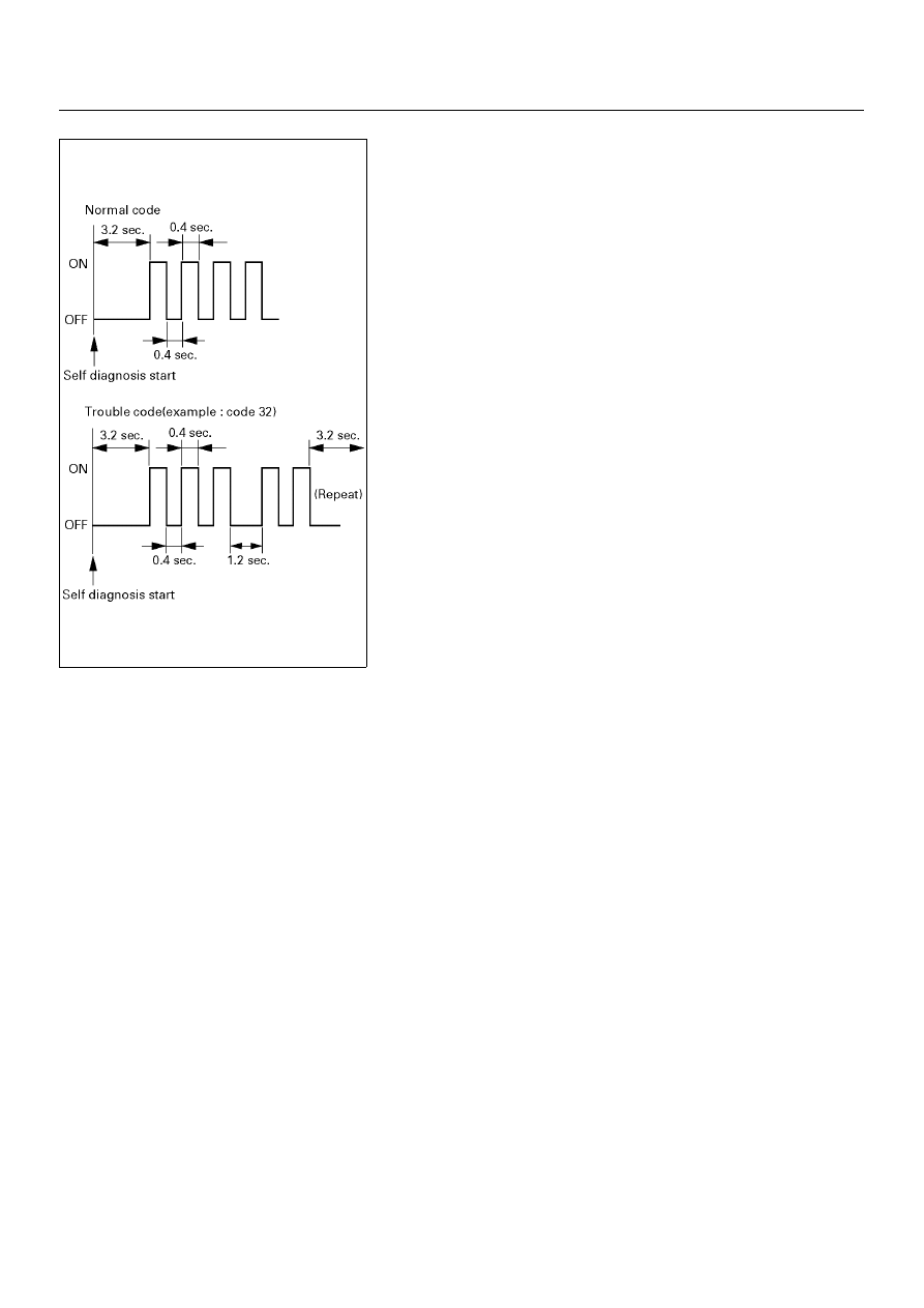
Indication Method:
1. Terminals No. 11 are No. 4 or 5 (ground) of data link
connector are short circuited.
2. Turn the ignition key to the ON position.
3. In case there no trouble, normal code is indicated.
4. In case a plurality of trouble codes have occurred at a time,
each code is indicated three times in numerical order.
NOTE:
Power line runs through data link connector.
Be careful shorting with a lead wire, etc.
(The vehicle side of control module may be damaged.) For
identification of trouble code, connect Tech2 to data link
connector.
Clear of trouble code memory
1. Clear the trouble code memory using F1: Clear DTC
Information for Tech2.
2. After more than 1 second has elapsed after the ignition key
has been turned ON, short between No. 11 and No. 4 or 5
(ground) of data link connector. Then, after 1 second, but
within 6 seconds, discontinue shorting.