Content .. 2481 2482 2483 2484 ..
Opel Frontera UBS. Manual - part 2483
6H – 2 ENGINE SPEED CONTROL
GENERAL DESCRIPTION
2
1
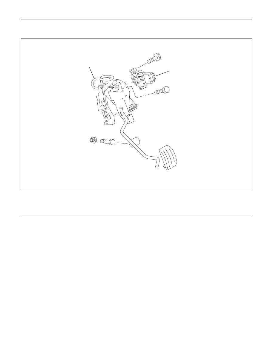
101R200006
Engine control has been changed from the control
cable system to an electronically controlled TP (Throttle
Position) sensor.
The TP sensor is a potentiometer (Variable resistance)
type and installed to the accelerator pedal bracket.
A voltage of 5 V is always applied from the ECM
(Electronic Control Module) to the TP sensor so that the
operating angle of the accelerator pedal can be
detected from a change in voltage.
Further, this sensor is equipped with an accelerator
switch which sends signals to the ECM when the
accelerator pedal is stepped on.
This switch remains on and turns off only when the
accelerator pedal is stepped on.
All vehicles have no throttle cable, and therefore, a
return spring is provided on the accelerator pedal and a
return cable assembly having the sliding resistance of a
cable is used to give the pedal a feeling.
To meet the newly adopted electronic control system,
the idling control button has been dropped.
Legend
(1)
Accerator Position Sensor
(2)
Return Cable