Opel Frontera UBS. Manual - part 2405


  Index      Opel     Opel Frontera UBS - service repair manual 1998-2002 year


Search            


Content   ..  2403  2404  2405  2406   ..


Opel Frontera UBS. Manual - part 2405


6A – 94 ENGINE MECHANICAL

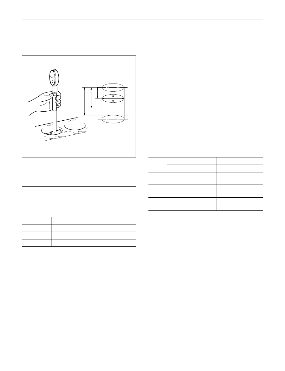
Cylinder Bore Measurement

1. Use a cylinder gauge to measure the cylinder bore

measuring direction for thrust and radial at
measuring points.

Legend

Measuring Point 1; 20 mm

2; 90 mm
3; 160 mm

2. Select the right piston grade by the averaged

cylinder bore measurement (maximum and
minimum value eliminated).

Cylinder bore diameter

mm(in)

Grade mark

Standard

A

95.421 – 95.430 (3.7567 – 3.7571)

B

95.431 – 95.440 (3.7571 – 3.7575)

C

95.441 – 95.450 (3.7575 – 3.7579)

3. If measured values exceed the limit, replace or

adjust the cylinder block honing or boring.

Limit 95.950 mm (3.7776 in)

4. Boring of the cylinder bore is allowed until it is 

0.5 mm (0.0197 in) diameter and oversized piston
is available as a service part.

Boring Cylinder Block

1. Use an oversized piston on the basis of above

mentioned cylinder using the largest inside
diameter.

2. Measure the piston outside diameter at right angles

with piston pin at a piston grade measuring point
69.75 mm (2.7461 in) from piston top surface and
calculate a inside diameter for cylinder boring.

3. Calculation of cylinder bore boring.

D + C – H (mm)

D; Outside diameter piston (mm)
C; Clearance between Cylinder bore and piston 
0.092 – 0.110 mm (0.0036 – 0.0043 in)
H; Honing allowance
Less than 0.03 mm (0.0012 in)

The oversize pistons are available three grades.

4. Honing the cylinder bore after boring.
5. Measure cylinder bore after honing.

Difference between each cylinder bore

Less than 0.02 mm (0.0008 in)

Cylinder bore and piston grade (After boring)

mm(in)

Grade

Oversize Piston

Bore

Mark

Outside Diameter

Diameter

A

95.820 – 95.829

95.921 – 95.930

(3.7724 – 3.7728)

(3.7764 – 3.7768)

B

95.830 – 95.839

95.931 – 95.940

(3.7728 – 3.7732)

(3.7768 – 3.7772)

C

95.840 – 95.849

95.941 – 95.950

(3.7732 – 3.7736 )

(3.7772 – 3.7776)

REASSEMBLY

1. Cylinder Block
2. Piston Cooling Oil Pipe

1) Fix the cooling jet pipes with knock pins on the

cylinder block.

2) Install the oil pipe for piston cooling in the

cylinder block, tightening a relief valve (1) and
four joint bolts (2) to the specified torque.
If oil jet pipe is forcibly assembled, the end of oil
jet may bend. It could make it impossible to
supply oil to the piston cooling hole, sometimes
causing piston seizure.
Sufficient care should be taken to pipe assembly
work.

3

2

1

012RW117

ENGINE MECHANICAL 6A – 95

Oil pipe fixing bolts

M8: 20 N·m (2.0 kg·m/14 lb ft)
M6: 8 N·m (0.8 kg·m/69 lb in)

Relief valve fixing bolts : 30 N·m (3.1 kg·m/22 lb ft)

CAUTION: After installing the piston assembly,
check and see that there is appropriate clearance
between pistons and oil jet pipes by rotating
crankshaft slowly.

3. Crankshaft

1) Install the main bearings to the cylinder body

and the main bearing caps.

2) Be sure that they are positioned correctly.
3) Apply new engine oil to the upper and lower

main bearing faces.

4) Carefully mount the crankshaft.

5) Apply engine oil to the thrust washer.
6) Assemble the thrust washer to the  No. 3

bearing journal. The oil grooves must face the
crankshaft.

4. Main Bearing Cap Assembly

1) Install the main bearing caps with the main

bearing cap head arrow mark facing the front of
the engine.

2) Apply engine oil to the main bearing cap bolts.
3) Tighten the main bearing cap bolts to the

specified torque a little at a time in the sequence
shown in the illustration.

Torque: 167 N·m (17.0 kg·m/123 lb ft)

3

2

1

012RW076

012RW038

012RW047

1

2

3

4

5

012RW025

6A – 96 ENGINE MECHANICAL

NOTE: Check to see that the crankshaft turns
smoothly by rotating it manually.

4. Piston Assembly

1) Refer to “Piston and connecting rod” in this

manual.

5. Cylinder Block Side Cover Right and Left
6. Balance Shaft Right.

Apply new engine oil to the balance shaft (right) and
insert it into cylinder block.

7. Timing Gear Case

1) Cut out the liquid gasket forced out from

between the contact surface of cylinder block
and crankshaft.

2) Apply liquid gasket (TB1207B or equivalent) to

the fitting surface of the cylinder block and
crankcase.

3) Install timing gear case with gasket to cylinder

block and tighten to specified torque.

Torque: 20 N·m (2.0 kg·m/14 lb ft)

8. Crankshaft Gear

Force key into crankshaft and force in crankshaft
gear along the key groove using a special tool (1)
with the crank gear (2) timing mark facing outside.

9. Install timing gear align the timing mark on each

timing gear.
For alignment of timing marks refer to “Timing
Gear” in this manual.

NOTE: Remove the locking bolt or pin from idle gear A
and idle gear C.

10. Assembling the gear case cover.

1) Install the oil seal on the oil pump assembly

before installing the gear case cover.

2) Apply liquid gasket to timing gear case.

NOTE: Be sure to apply liquid gasket evenly.

8

4

1

5

9

6

10

2

3

7

012RW027

012RW064

1

2

2

012RW066

2

2~2.5mm

2~2.5mm

Apply liquid gasket around inside 
of the bolt hole

Bolt hole

Inside

Outside

F06HX00001

ENGINE MECHANICAL 6A – 97

11. Use the special tool to install the crankshaft front oil

seal to timing gear case.
Front Oil Seal Installer: 5-8840-2061-0

1) Check fit-of the oil seal and gear case cover at

the front end.

Standard: 0.5 – 2.5 mm (0.0197 – 0.0984 in)

NOTE: Apply engine oil to oil seal lip before installation
of the seal.

12. Install the oil pan assembly to original position and

tighten to specified torque.

Torque: 22 N·m (2.2 kg·m/16 lb ft)
13. Crankshaft Rear Oil Seal

1) Tighten the adapter to the crankshaft rear end

with 2 bolts.

2) Insert the oil seal into the adapter.

NOTE: Apply oil to oil seal lip.

3) Insert the sleeve into the adapter and tighten it

with a bolt (M12 x 1.75L = 70) until the adapter
hits the sleeve.

4) Remove the adapter and the sleeve.
5) With the seal pressed in, check the dimension of

the oil seal outside end and crankshaft end.

Standard Dimension = 12.5 ± 0.3 mm

Oil Seal Installer: 5-8840-2359-0

14. Cylinder Block Rear Plate (A/T Model)

1) Tighten the cylinder block rear plate fixing bolts

to the specified torque.

Torque: 97 N·m (9.9 kg·m/72 lb ft)
15. Flywheel Housing (M/T Model)

1) Install flywheel housing aligned with the dowel

pin on the cylinder block.

2) Tighten the flywheel housing fixing bolts to the

specified torque.

Torque: 97 N·m (9.9 kg·m/72 lb ft)
16. Flywheel

1) Refer to “Crankshaft” in this manual.

17. Cylinder Head Assembly

1) Refer to “Cylinder Head” in this manual.

015RW074

12.5 + 0.3

012RW067


Content   ..  2403  2404  2405  2406   ..