Opel Frontera UBS. Manual - part 2352


  Index      Opel     Opel Frontera UBS - service repair manual 1998-2002 year


Search            


Content   ..  2350  2351  2352  2353   ..


Opel Frontera UBS. Manual - part 2352


6E–444

6VE1 3.5 ENGINE DRIVEABILITY AND EMISSIONS

Diagnostic Trouble Code (DTC) P1636 PCM RAM Stack

Circuit Description

The powertrain control module (PCM) monitors
unexpected PCM reset. This will not turn on MIL light on,
only record code DTC P1636.

Conditions for Setting the DTC

D

Clock or COP (Computer Operating Properly) reset.

Action Taken When the DTC Sets

D

The PCM will not illuminate the malfunction indicator
lamp (MIL).

D

The PCM will store conditions which were present
when the DTC was set as Failure Records only. This
information will not be stored as Freeze Frame data.

Conditions for Clearing the MIL/DTC

D

The PCM will turn the MIL “OFF” on the third
consecutive trip cycle during which the diagnostic has
been run and the fault condition is no longer present.

D

A history DTC P1636 will clear after 40 consecutive
warm-up cycles have occurred without a fault.

D

DTC P1636 can be cleared by using the Tech 2 “Clear
Info” function or by disconnecting the PCM battery
feed.

Diagnostic Aids

Check for the following conditions:

D

P1636 stored alone does not need diagnosis. Clear
DTC code.

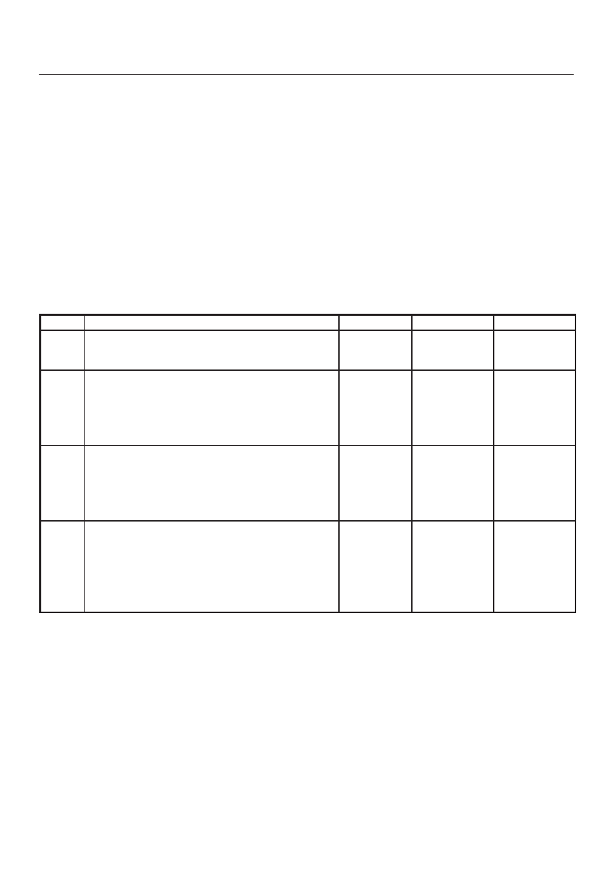
DTC P1636 – PCM RAM Stack


Step

Action

Value(s)

Yes

No

1

Was the “On-Board Diagnostic (OBD) System Check”
performed?

Go to Step 2

Go to 

OBD

System

Check

2

1. Ignition is “ON”.
2. Install the Tech 2.
3. Start the engine and let it Idle.
4. On the Tech 2, select “DTC info”.

Does the Tech 2 indicate DTC P1636 failed?

Go to 

Step 3

Check the

Procedure

Refer to

Diagnostic

Aids

3

1. Ignition is “ON”.
2. Clear DTC P1636 by using the Tech 2 “Clear Info”.
3. Start the engine and let it Idle.
4. On the Tech 2, select “DTC info”.

Does the Tech 2 indicate DTC P1636 failed?

Go to 

Step 4

Check the

Procedure

Refer to

Diagnostic

Aids

4

1. Check for aftermarket electronics, such as

transceiver, stereos, and anti theft devices. They
may radiate EMI into the control system if they are
improperly installed. (This may cause a false sensor
reading and turn on the MIL.)

2. If a problem is found, repair as necessary.

Was a problem found?

Verify repair

6E–445

6VE1 3.5L ENGINE DRIVEABILITY AND EMISSIONS

Diagnostic Trouble Code (DTC) 

P1639 Reference Voltage # 2 Circuit Fault

D06RY00075

Circuit Description

The TP sensor # 1 shares a 5 Volt reference with the
PCM.
If the PCM detects the 5 Volt reference for the AP sensor
# 1 is failure, DTCP1635 will be set.

Conditions for setting the DTC

D

The ignition is “ON”.

D

The 5 Volt reference voltage for the AP sensor # 1 is
less than 4 volts.

D

The 5 Volt reference voltage for the AP sensor # 1 is
more than 5 volts.

Action Taken When the DTC Sets

D

The PCM will not illuminate the malfunction indicator
lamp (MIL) .

D

The PCM will store condition which were present when
the DTC was set as Freeze Frame and in the Failure
Records data.

Conditions for Clearing the MIL/DTC

D

The PCM will turn the MIL “OFF” on the third
consecutive trip cycle during which the diagnostic has
been run and the fault condtion is no longer present.

D

A history DTC P1639 will clear after 40 cosecutive trip
cycle during which the warm up cycles have occurred
without a fault.

D

DTC P1639 can be cleared using the Tech 2 “Clear
Info” function or by disconnecting the PCM battery
feed. Tech2 “ Clear Info” function or by disconnecting
the PCM battery feed.

6E–446

6VE1 3.5 ENGINE DRIVEABILITY AND EMISSIONS

Diagnostic Trouble Code (DTC) 

P1639 Reference Voltage # 2 Circuit Fault


Step

Action

Value(s)

Yes

No

1

Was the “On-Board(OBD)System Check” performed?

Go to

 Step 2

Go to

 OBD

System

Check

2

1. Connect a DVM between the 5volt reference curcuit

and the AP1, AP2 and AP3 sensor ground curcuit.

2. Check the voltage using a DVM.

Is the voltage near the specified value?

5V

Varify repair

Go to

 Step 3

3

1. Check the APS1, APS2 and APS3 5 volt reference

curcuit.

2. If the curcuit is open or shorted, repair it as

necessary.

Was the curcuit open or short?

Varify repair

Go to

 Step 4

4

1. Check the AP1, AP2 and AP3 sensor ground

curcuit.

2.  If the curcuit is open or shorted, repair it as

necessary.

Was the curcuit open or short?

Varify repair

Go to

 Step 5

5

1. Observe the battery voltage and circuit.
2. If a problem found, repair it as necessary.

Was a problem found?

Verify repair

Go to

 Step 6

6

Replace the PCM.

IMPORTANT: The replacement PCM must be
programmed.

Refer to ON–Vehicle Service in Power Control Module
and Sensors for procedures.

And also refer to latest Service Bulletin. Check to see
if the latest software is released or not.

And then Down Load the LATEST PROGRAMMED
SOFTWARE to the replacement PCM.

Is the adtion complete?

Verify repair

6E–447

6VE1 3.5L ENGINE DRIVEABILITY AND EMISSIONS

Diagnostic Trouble Code (DTC) 

P1640 Driver-1-Output Circuit Fault (ODM)

Circuit Description

Output driver modules (ODMs) are used by the
powertrain control module (PCM) to turn “ON” many of
the current-driven devices that are needed to control
various engine and transmission functions.  Each ODM is
capable of controlling up to 7 separate outputs by
applying ground to the device which the PCM is
commanding “ON”.
Unlike the Quad Driver Modules (QDMs) used in prior
model years, ODMs have the capability of diagnosing
each output circuit individually.  DTC P1640 set indicates
an improper voltage level has been detected on an ODM
output.
Since A/C is an option, No A/C will cause the air
conditioning clutch relay output to always fail.  If a fault is
seen on the air conditioning clutch relay output, it will not
be logged as a fault until the A/C request input interrupts a
high voltage, indicating that A/C has been installed.

Conditions for Setting the DTC

D

Ignition “ON”.

D

Engine running.

D

Ignition voltage is above 13.2 volts for 4 seconds.

D

Output voltage does not equal ignition voltage when
output is “OFF” or output voltage is not less than 1 volt
when output is “ON”.

D

Above conditions occur for at least 1 second.

Action Taken When the DTC Sets

D

The PCM will not illuminate the malfunction indicator
lamp (MIL).

D

The PCM will store conditions which were present
when the DTC was set as Failure Records only.  This
information will not be stored as Freeze Frame data.

Conditions for Clearing the MIL/DTC

D

A history DTC P1640 will clear after 40 consecutive
warm-up cycles occur without a fault.

D

DTC P1640 can be cleared by using the Tech 2 “Clear
Info” function or by disconnecting the PCM battery
feed.

Diagnostic Aids

Check for the following conditions:

D

Poor connection at PCM – Inspect harness connectors
for backed-out terminals, improper mating, broken
locks, improperly formed or damaged terminals, and
poor terminal-to-wire connection.

D

Damaged harness – Inspect the wiring harness for
damage,  If the harness appears to be OK, disconnect
the PCM, turn the ignition “ON” and observe a
voltmeter connected to the suspect driver circuit at the
PCM harness connector while moving connectors and
wiring harnesses related to the MIL.  A change in
voltage will indicate the location of the fault.

D

Poor connection at component – Examine for
damaged connectors, unplugged connector, or
damaged terminals at the following locations:
Instrument cluster harness, canister purge solenoid,
A/C clutch relay.  An open ignition feed circuit at any of
these components will cause DTC P1640 to be set.

Reviewing the Failure Records vehicle mileage since the
diagnostic test last failed may help determine how often
the condition that caused the DTC to be set occurs.  This
may assist in diagnosing the condition.

DTC P1640 – Driver-1-Output Circuit Fault (ODM)


Step

Action

Value(s)

Yes

No

1

Was the “On-Board Diagnostic (OBD) System Check”
performed?

Go to 

Step 2

Go to 

OBD

System

Check

2

Check the fuse for the driver circuit that was shown as
faulty.

Was the fuse blown?

Go to 

Step 3

Go to 

Step 4

3

1. Check for a short to ground between the fuse and

the affected component.

2. Replace the fuse after making any necessary

repairs.

Is the action complete?

Verify repair

4

Disconnect the PCM connector for the affected driver
circuit.

Is there any damage to the PCM pin or connector?

Go to 

Step 5

Go to 

Step 6

5

Repair the damaged pin or terminal.

Is the action complete?

Verify repair

6

Were either of the lamp circuits for “Check Engine” or
“Check Trans” indicated as faulty by the Tech 2?

Go to 

Step 7

Go to 

Step 13


Content   ..  2350  2351  2352  2353   ..