Opel Frontera UBS. Manual - part 227
POWER ASSISTED BRAKE SYSTEM 5C – 53
DISASSEMBLY
1. Guide Bolt
2. Lock Bolt
3. Dust Boot; Guide Bolt and Lock Bolt
4. Dust Boot Ring
•
Using a small screwdriver, remove the dust boot
ring.
REBUILDING THE CALIPER
4
6
5
7
3
8
3
2
1
9
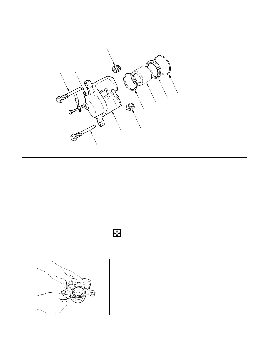
Disassembly Steps
1.
Guide bolt
2.
Lock bolt
3.
Dust boot; guide bolt and lock bolt
4.
Dust boot ring
5.
Piston
6.
Dust boot; piston
7.
Piston seal
8.
Bleeder with cap
9.
Caliper body
Reassembly Steps
9.
Caliper body
8.
Bleeder with cap
7.
Piston seal
5.
Piston
6.
Dust boot; piston
4.
Dust boot ring
3.
Dust boot; guide bolt and lock bolt
2.
Lock bolt
1.
Guide bolt