Opel Frontera UBS. Manual - part 223


  Index      Opel     Opel Frontera UBS - service repair manual 1998-2002 year


Search            


Content   ..  221  222  223  224   ..


Opel Frontera UBS. Manual - part 223


POWER ASSISTED BRAKE SYSTEM  5C – 37

INSTALLATION

7. Switch

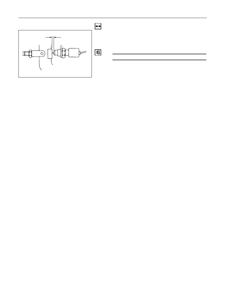
Adjust the stoplight switch to the specified
clearance (between switch housing and brake
pedal) by rotating the switch housing.

Clearance

mm (in)

0 – 0.2 (0 – 0.008)

NOTE:
While adjusting the installation of the stoplight
switch, make sure that the threaded part of the
stoplight switch does not push the brake pedal.

6. Lock Nut

5. Stoplight Switch Connector

4. Instrument Panel Driver Lower Cover Assembly

3. Lower Cluster Assembly

2. Front Console Assembly

1. Shift Knob

(A)

5C – 38 POWER ASSISTED BRAKE SYSTEM

FLUID RESERVOIR TANK

2

4

1

3

Removal Steps

1.

Electrical connector

2.

Retainer

3.

Fluid reservoir

4.

O-ring

Installation Steps

To install, follow the removal steps in the
reverse order.

REMOVAL

NOTE:
Before removing fluid reservoir, remove brake fluid
from fluid reservoir.

1. Electrical Connector

2. Retainer

3. Fluid Reservoir

The fluid level sensor is built into the fluid
reservoir. It cannot be removed for servicing.

4. O-ring

INSTALLATION

To install, follow the removal steps in the reverse
order, noting the following points;

4. O-ring

O-ring must be set onto the fluid reservoir, before
installing fluid reservoir.

Retainer

Fluid reservoir

O-ring

POWER ASSISTED BRAKE SYSTEM  5C – 39

MASATER CYLINDER ASSEMBLY

6

2

1

5

3

4a

4b

Removal Steps

1.

Electrical connector

2.

Brake pipes

3.

2 attaching nuts

4a. P&B valve and bracket
4b. 3-way connector and bracket (Vehicle

with LSPV only)

5.

Master cylinder

6.

Spacer and 2 gaskets

Installation Steps

To install, follow the removal steps in the
reverse order.

This illustration is based on the LHD model.

330RW015

5C – 40 POWER ASSISTED BRAKE SYSTEM

REMOVAL

CAUTION:
When removing master cylinder from vacuum
booster, be sure to get rid of the internal negative
pressure of the vacuum booster (by, for instance,
disconnecting vacuum hose) in advance.
If any negative pressure remains in the vacuum
booster, the piston may possibly come out when the
master cylinder is being removed, letting the brake
fluid run out.
While removing master cylinder, further, do not hold
the piston as it can be easily pulled out.
Outside surface of the piston is the surface on which
seals are to slide. Care should be taken to keep the
surface free of cuts and dents.

1. Electrical Connector

2. Brake Pipes

After disconnecting the brake pipe, cap or tape
the openings of the brake pipe to prevent the
entry of foreign matter.

3. 2 Attaching Nuts

4a. P & B Valve and Bracket

4b.3-way Connector and Bracket (Vehicle with LSPV

Only)

5. Master Cylinder

6. Spacer and 2 Gaskets

INSTALLATION

6. Spacer and 2 Gaskets

5. Master Cylinder

When replacing the master cylinder or vacuum
booster or both, always measure the vacuum
booster push rod protrusion and adjust it as
necessary. (Refer to Vacuum Booster Assembly in
this section.)

4a. P & B Valve and Bracket

4b.3-way Connector and Bracket (Vehicle with LSPV

Only)

3. 2 Attaching Nuts

Tighten the attaching nuts to the specified torque.

Attaching Nut Torque

N·m (kg·cm / lb·in)

13 (130 / 113)

2. Brake Pipes

Tighten the brake pipe to the specified torque.

Brake Pipe Torque

N·m (kg·m / lb·ft)

Master Cylinder Side

Others

12 (1.2 / 9)

16 (1.6 / 12)

1. Electrical Connector


Content   ..  221  222  223  224   ..