Opel Frontera UBS. Manual - part 2222


  Index      Opel     Opel Frontera UBS - service repair manual 1998-2002 year


Search            


Content   ..  2220  2221  2222  2223   ..


Opel Frontera UBS. Manual - part 2222


6A–78

ENGINE MECHANICAL (6VE1 3.5L)

015RS026

D

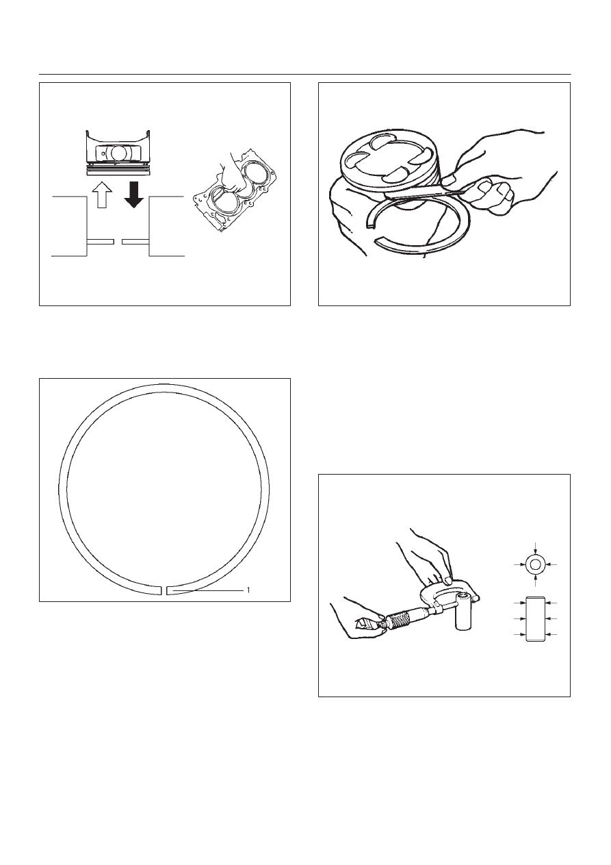
Positioning mark (1) is painted as shown in the
illustration.

Marked T : No.1 Compression ring

Marked T2 : No.2 Compression ring

015RS027

2. Measure the clearance between the piston ring

groove and the piston ring with a feeler gauge. If the
piston ring groove / piston ring clearance exceeds the
specified limit, the piston must be replaced.

Compression Ring Clearance
Standard : 0.025 mm–0.065 mm

(0.0006 in.–0.0015 in)

Limit : 0.1mm (0.0059 in)

015RS028

Piston Pin

NOTE: Do not reuse the old piston pin.

1. Use a micrometer to measure the new piston pin

outside diameter in both directions at three different
positions.

2. Measure the inside diameter of the connecting rod

small end. If the fitting interference between the small
end and pin does not conform to the specified value,
the connecting rod must be replaced.

Standard : 0.023 mm–0.038 mm (0.0009
in–0.0015 in)

015RS029

6A–79

ENGINE MECHANICAL (6VE1 3.5L)

3. Insert the new pin into the piston and rotate it. If the

pin rotates smoothly with no backlash, the clearance
is normal. If there is backlash or roughness, measure
the clearance. If the clearance exceeds the specified
limit, the piston must be replaced.

Clearance
Standard : 0.010 mm–0.017 mm

(0.0004 in.–0.0007 in)

Limit : 0.040 mm (0.0016 in)

Connecting Rods

1. Check the connecting rod alignment If either the bend

or the twist exceeds the specified limit, the connecting
rod must be replaced.

Bend per 100 mm (3.937 in)
Limit: 0.15 (0.0059)
Twist per 100 mm (3.937 in)
Limit: 0.20 (0.0078)

015RS030

2. Measure the connecting rod thrust clearance. Use a

feeler gauge to measure the thrust clearance at the
large end of the connecting rod If the clearance
exceeds the specified limit, the connecting rod must
be replaced.

Standard : 0.16 mm–0.35 mm

(0.0063 in.–0.0138 in)

Limit : 0.40 mm (0.0157 in)

015RS031

3. Measure the oil clearance between the connecting

rod and the crankshaft.
1. Remove the connecting rod cap nuts and the rod

caps (12).
Arrange the removed rod caps in the cylinder
number order.

2. Clean the rod bearings and the crankshaft pins.

3. Carefully check the rod bearings. If even one

bearing is found to be damaged or badly worn, the
entire bearing assembly must be replaced as a
set. Reinstall the bearings in their original
positions. Apply plastigage to the crank pin.

015RS032

4. Reinstall the rod caps (12) to their original

positions.
Tighten the rod cap nuts.

Torque: 54 N·m (5.5 kg·m/40 lb ft)

NOTE: Do not allow the crankshaft to rotate.

6A–80

ENGINE MECHANICAL (6VE1 3.5L)

5. Remove the rod caps.

6. Measure the width of the plastigage and

determine the oil clearance. If the oil clearance
exceeds the limit, replace the rod bearing as a
set.

Standard : 0.019 mm–0.043 mm

(0.0007 in–0.0017 in)

Limit : 0.08 mm (0.0031 in)

015RS008

7. Clean the plastigage from the bearings and the

crankshaft pins.

Con–rod Bearing Selection

Select and install the new connecting rod bearings,
paying close attention to the connecting rod big end
diameter size mark (1).

NOTE: Take care not to confuse the alignment mark (2)
and the size mark (1) during the installation procedure.

015RS034

1 Size Mark

Big end Bore

Diameter

Crankshaft Pin

Diameter

Connecting Rod

Bearing Thickness

(Reference)

Color of

Size

Mark

Oil Clearance

(Reference)

A

56.994-57.000 mm

(2.2439-2.2441 in)

1.512-1.516 mm

(0.0595-0.0597 in)

Yellow

0.025-0.054 mm

(0.0010-0.0021 in)

B

56.988-56.994 mm

(2.2436-2.2439 in)

53.922-53.937 mm

(2.1229-2.1235 in)

1.508-1.512 mm

(0.0594-0.0595 in)

Green

0.027-0.056 mm

(0.0011-0.0022 in)

C

56.982-56.988 mm

(2.2434-2.2436 in)

1.504-1.508 mm

(0.0592-0.0594 in)

Pink

0.029-0.058 mm

(0.0011-0.0023 in)

Reassembly

1. Install connecting rod
2. Install piston
3. Install piston pin

D

Apply a thin coat of engine oil to the piston pin. Try to
insert the piston pin into the piston pin hole with
normal finger pressure.

NOTE: When  changing piston / connecting rod
combinations, do not change the piston / piston pin
combination and do not reuse the old piston pin.

D

Attach the piston to the connecting rod with the
piston front mark and the connecting rod front mark
on the same side.

015RS036

6A–81

ENGINE MECHANICAL (6VE1 3.5L)

D

With 5-8840-0551-0 Piston pin service set and a
press, press fit the piston pin.

NOTE: Heat the connecting rod small end to a suitable
temperature to ensure smooth installation.

015RX001

Legend

(1) Press Ram
(2) Piston
(3) Connecting Rod
(4) Piston Pin

4. Install piston ring with the piston ring expander.

D

Install piston rings in the following sequence.

015RS038

1. Oil ring

1. Expander ring
2. Upper side rail
3. Lower side rail

2. 2nd compression ring
3. 1st compression ring

D

The compression rings must be set with the T or T2
mark facing up.

Marked T : No.1 Compression ring

Marked T2 : No.2 Compression ring

015RS027

D

After installation, apply engine oil to the entire
circumference of the piston rings. Check to see that
all the rings rotate smoothly.

5. Install piston and connecting rod assembly.

D

Insert the bearings into the connecting rods and
caps. Apply new engine oil to the bearing faces and
nuts.

D

Tighten the connecting rod cap nuts

Torque : 54 N·m (5.5 kg·m/40 lb ft)

NOTE: Do not apply engine oil to the bearing back faces.

6. Oil gallery, refer to “Crankshaft and main bearing” in

this manual.

7. Oil strainer and O-ring.
8. Oil pipe and O-ring.
9. Install crankcase with oil pan, refer to “Oil pan and

Crankcase” in this manual.

10. Install cylinder head gasket.

11. Install Cylinder head assembly.

D

Refer to “Cylinder head” in this manual.


Content   ..  2220  2221  2222  2223   ..