Opel Frontera UBS. Manual - part 2221


  Index      Opel     Opel Frontera UBS - service repair manual 1998-2002 year


Search            


Content   ..  2219  2220  2221  2222   ..


Opel Frontera UBS. Manual - part 2221


6A–74

ENGINE MECHANICAL (6VE1 3.5L)

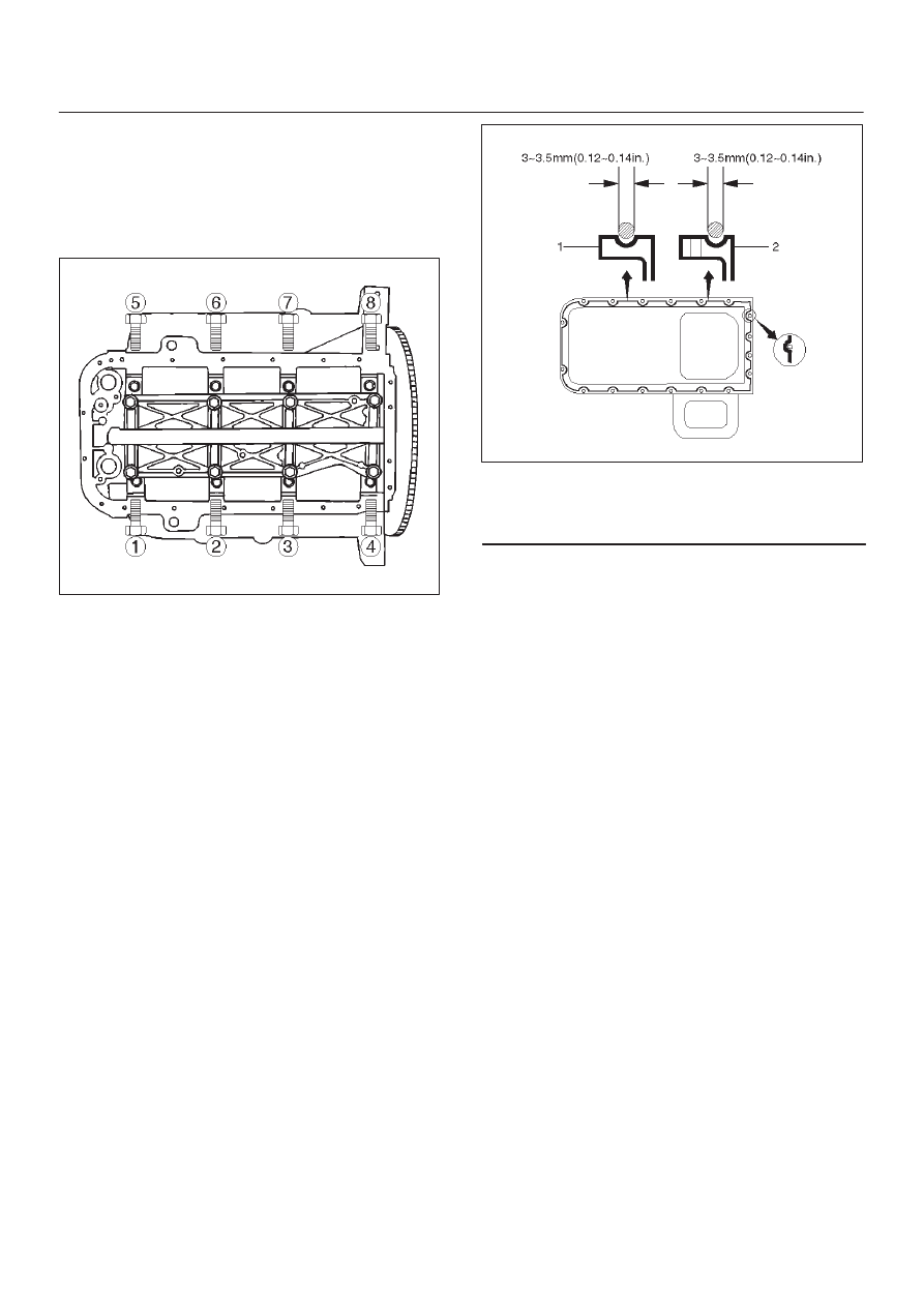
6. Cylinder block side bolts (6)

D

Tighten all the bolts to the specified torque in the
order shown.

NOTE: Do not apply engine oil to the crank case side
bolts.

Torque: 39 N·m (4.0 kg·m/29 lb ft)

012RS001

7. Install oil pump assembly (5), refer to “Oil pump” in

this manual.

8. Install oil strainer and O-ring (4).
9. Install oil pipe and O-ring (3) and tighten the bolts.

Torque: 25 N·m (2.6 kg·m/18 lb ft)

10. Install crankcase with oil pan (2).

1. Completely remove all residual sealant, lubricant

and moisture from the sealing surfaces. The
surfaces must be perfectly dry.

2. Apply a correct width bead of sealant (TB—

1207C or its equivalent) to the contact surfaces of
the oil pan. There must be no gaps in the bead.

3. The crankcase assembly must be installed within

5 minutes after sealant application.

4. Tighten the bolts and nuts to the specified torque.

Torque : 10 N·m (1.0 kg·m/87 lb in)

013RW010

Legend

(1) Portion Between Bolt Holes
(2) Bolt Hole Portion

11. Install cylinder head assembly, refer to “Cylinder

head” in this manual.

6A–75

ENGINE MECHANICAL (6VE1 3.5L)

Piston and Connecting Rod

Piston, Connecting Rod and Associate Parts

015RW019

Legend

(1) Cylinder Head Assembly
(2) Cylinder Head Gasket
(3) Crankcase with Oil Pan
(4) Oil Pipe and O-ring
(5) Oil Strainer and O-ring
(6) Oil Gallery

(7) Piston and Connecting Rod Assembly
(8) Piston Ring
(9) Piston Pin

(10) Piston

(11) Connecting Rod

(12) Connecting Rod Cap

Disassembly

1. Remove cylinder head assembly (1). Refer to

“Cylinder Head Removal” in this manual.

2. Remove cylinder head gasket (2).
3. Remove crankcase with oil pan (3). Refer to“Oil Pan

and Crankcase” in this manual.

4. Remove oil pipe and O-ring (4).

5. Remove oil strainer and O-ring (5).
6. Remove oil gallery (6).
7. Remove connecting rod cap with connecting rod

lower bearing (12).

8. Remove piston and connecting rod assembly (7).

NOTE: Before removing piston and connecting rod
assembly, measure thrust clearance.

6A–76

ENGINE MECHANICAL (6VE1 3.5L)

015RS031

D

Remove any ridge or carbon build up from the top
end of the cylinder.

9. Remove the piston rings (8) with a piston ring

expander. Arrange the removed piston rings in the
cylinder number order.

015RS022

10. Remove the piston pin (9) using 5-8840-0551-0

piston pin service set and piston support with a press.

NOTE: Keep the parts removed from each cylinder
separate.  All parts must be reinstalled in their original
positions.  Heating the connecting rod will permit easy
removal of the piston pin.

015RX001

Legend

(1) Press Ram
(2) Piston
(3) Connecting Rod
(4) Piston Pin

11. Piston (10)

12. Connecting rod (11)

Inspection and Repair

Pistons

Carefully clean away all the carbon adhering to the piston
head and the piston ring grooves.

NOTE: Never use a wire brush to clean the pistons.
Damage will result. Visually check each piston for
cracking, scoring, and other signs of excessive wear. If
any of the above conditions are found, the piston must be
replaced.

Piston Diameter

1. Measure the piston outside diameter with micrometer

at the piston grading position and a right angle to the
piston pin.
Piston grading position (from piston head)

Piston grading position : 43.0 mm (1.6929 in)

6A–77

ENGINE MECHANICAL (6VE1 3.5L)

015RV014

The size mark (1) for piston outside diameter is
represented as shown in Figure.

Outside Diameter
Size Mark A : 93.360 mm–93.370 mm

(3.6756 in–3.6760 in)

Size Mark B : 93.371 mm–93.380 mm

(3.6760 in–3.6764 in)

Size Mark C : 93.381 mm–93.390 mm

(3.6764 in–3.6768 in)

015RS025

Measure the cylinder bore inside diameter (refer to
“Cylinder Block” in this manual).

012RS002

Piston Rings

Any worn or damaged part discovered during engine
overhaul must be replaced with a new one.

1. Ring end gap measurement

D

Insert the piston ring into the bore.

D

Push the ring by the piston, at a right angle to the
wall, into the point at which the cylinder bore
diameter is the smallest.

D

Measure the ring end gap.

Compression Ring

1st ring

Standard:

0.300 mm–0.400 mm

(0.0118 in–0.0157 in)

Limit:

1.0 mm (0.0394 in)

2nd ring

Standard:

0.450 mm–0.600 mm

(0.0177 in–0.0236 in)

Limit:

1.2 mm (0.0472 in)

Oil ring

Standard:

0.150 mm–0.450 mm

(0.0059 in–0.0177 in)

Limit:

1.05 mm (0.0413 in)


Content   ..  2219  2220  2221  2222   ..