Content .. 2209 2210 2211 2212 ..
Opel Frontera UBS. Manual - part 2211
6A–34
ENGINE MECHANICAL (6VE1 3.5L)
014RW024
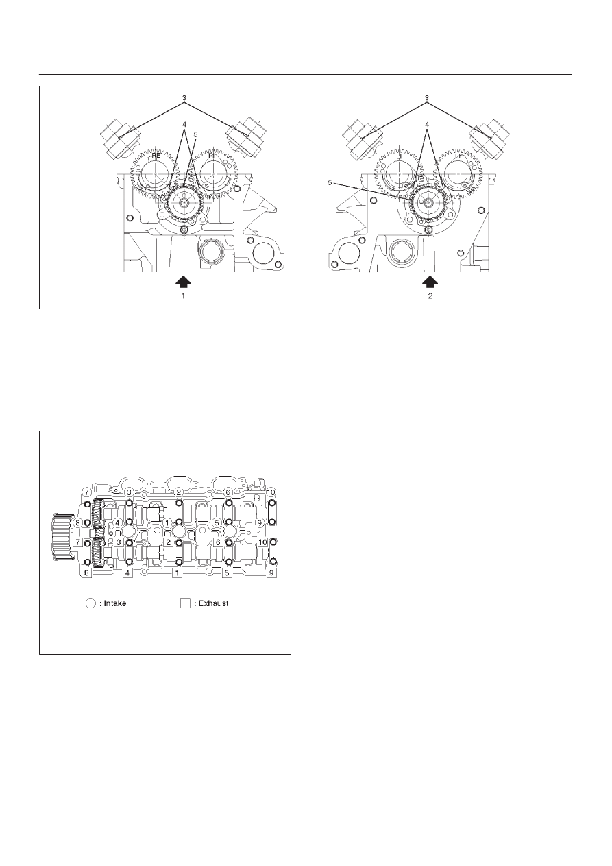
Legend
(1) Right Bank
(2) Left Bank
(3) Alignment Mark on Camshaft Drive Gear
(4) Alignment Mark on Camshaft
(5) Alignment Mark on Retainer
3. Tighten twenty bolts on numerical order an one
side bank as shown in the illustration.
Torque : 10 N·m (1.0 kg·m/87 lb in)
014RW031
5. Install cylinder head cover RH.
D
Refer to installation procedure for CYLINDER
HEAD COVER RH in this manual.
6. Install cylinder head cover LH.
D
Refer to installation procedure for CYLINDER
HEAD COVER LH in this manual.
7. Install timing belt.
D
Refer to installation procedure for TIMING BELT in
this manual.
8. Install crankshaft pulley.
D
Refer to installation procedure for CRANKSHAFT
PULLEY in this manual.