Content .. 2208 2209 2210 2211 ..
Opel Frontera UBS. Manual - part 2210
6A–30
ENGINE MECHANICAL (6VE1 3.5L)
014R100020
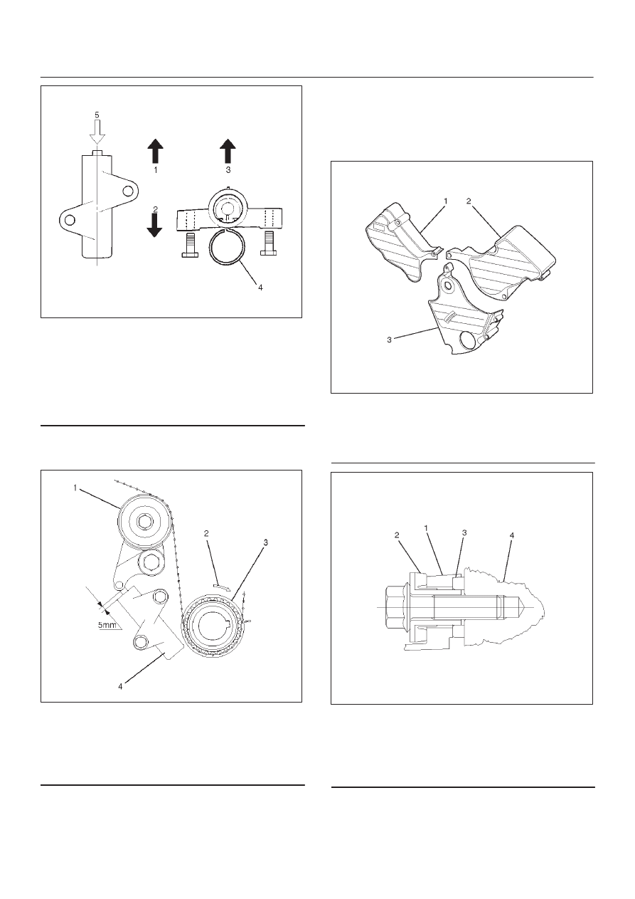
Legend
(1) Up Side
(2) Down Side
(3) Direction for Installation
(4) Locking Pin
(5) Apply a force of 980 N (100 kgf/220 lb) when
compressing the pusher rod.
After release the push rod from the locking pin,
the rod projection is approximate 5 mm (0.1969
in).
014R100032
Legend
(1) Tensioner Pulley
(2) Crankshaft Pulley Rotation Direction
(3) Crankshaft Pulley
(4) Pusher Assembly
3. Remove double clips or equivalent clips from
timing belt pulleys.
Turn the crankshaft pulley by six turns and check
for timing mark alignment.
3. Install timing belt cover.
Remove crankshaft pulley that was installed in step
1 item 5.
Tighten bolts to the specified torque.
Torque: 19 N·m (1.9 kg·m/14 lb ft)
020RW004
Legend
(1) Timing Belt Cover RH
(2) Timing Belt Cover LH
(3) Timing Belt Cover Lower
020RW003
Legend
(1) Timing Belt Cover
(2) Rubber Bushing
(3) Sealing Rubber
(4) Cylinder Body
4. Install crankshaft pulley using 5-8840-0133-0, hold
the crankshaft pulley and tighten center bolt to the
specified torque.
Torque : 167 N·m (17.0 kg·m/123 lb ft)