Opel Frontera UBS. Manual - part 2189


  Index      Opel     Opel Frontera UBS - service repair manual 1998-2002 year


Search            


Content   ..  2187  2188  2189  2190   ..


Opel Frontera UBS. Manual - part 2189


6E–329

ENGINE DRIVEABILITY AND EMISSIONS

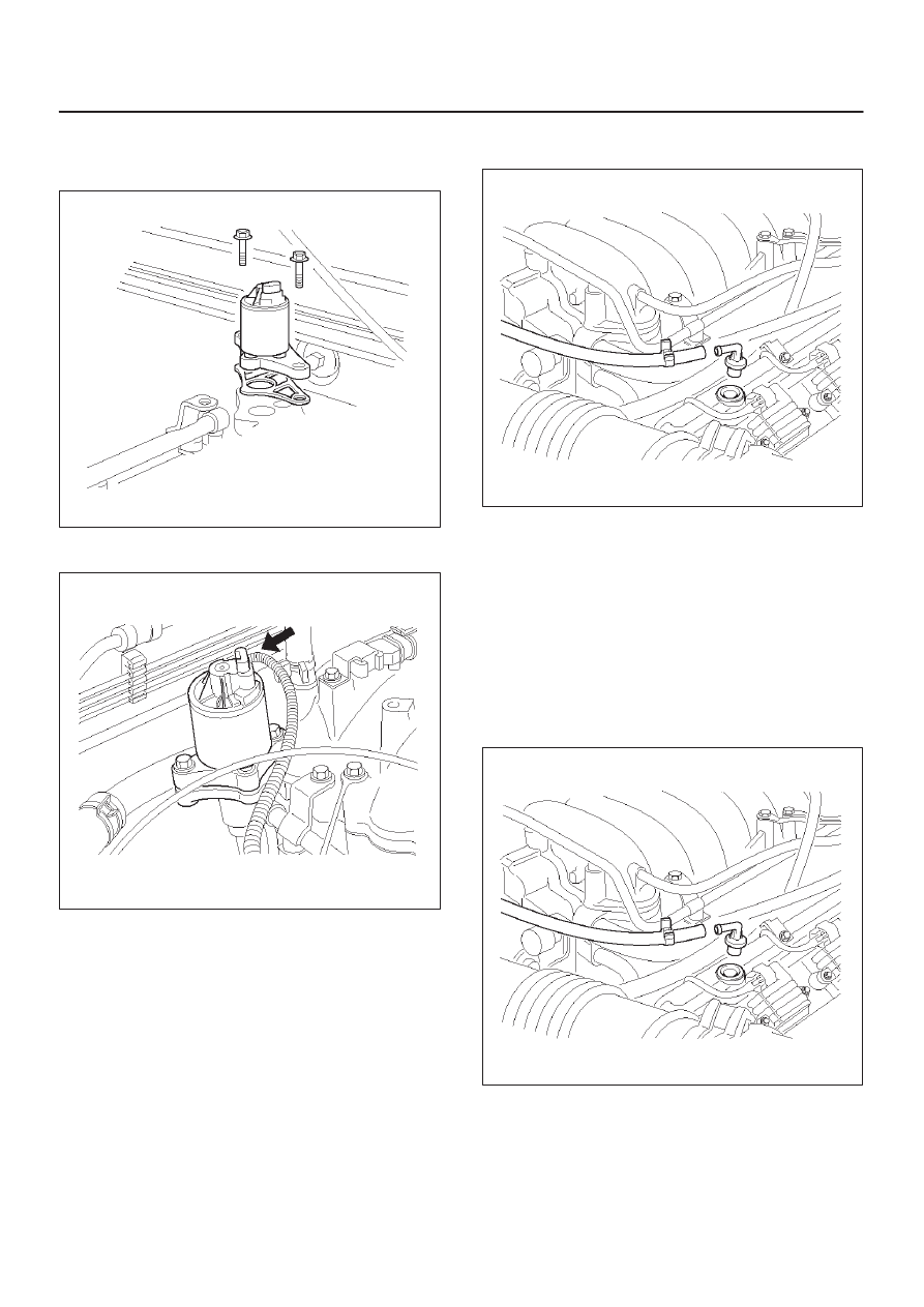
NOTE: It is possible to install the EGR valve rotated 180

°

from the correct position.  Make sure that the base of the
valve is placed so that it aligns with the mounting flange.

014RW098

4. Connect the electrical connector at the EGR valve.

014RW139

5. Connect the negative battery cable.

Positive Crankcase Ventilation

(PCV) Valve

Removal Procedure

1. Remove the vacuum hose at the PCV valve.

D

Slide the clamp back to release the hose.

2. Pull the PCV valve from the rubber grommet in the

right valve cover.

014RW097

Inspection Procedure

1. Shake the valve and listen for the rattle of the needle

inside the valve.

2. If the valve does not rattle, replace the valve.

Installation Procedure

1. Push the PCV valve into the rubber grommet in the

left valve cover.

2. Install the vacuum hose on the PCV valve and secure

the vacuum hose with the clamp.

014RW097

6E–330

ENGINE DRIVEABILITY AND EMISSIONS

Wiring and Connectors

Wiring Harness Service

The control module harness electrically connects the
control module to the various solenoids, switches and
sensors in the vehicle engine compartment and
passenger compartment.
Replace wire harnesses with the proper part number
replacement.
Because of the low amperage and voltage levels utilized
in powertrain control systems, it is essential that all wiring
in environmentally exposed areas be repaired with crimp
and seal splice sleeves.
The following wire harness repair information is intended
as a general guideline only.  Refer to 

Chassis Electrical for

all wire harness repair procedures.

Connectors and Terminals

Use care when probing a connector and when replacing
terminals.  It is possible to short between opposite
terminals.  Damage to components could result.  Always
use jumper wires between connectors for circuit
checking.  NEVER probe through Weather-Pack seals.
Use an appropriate connector test adapter kit which
contains an assortment of flexible connectors used to
probe terminals during diagnosis.  Use an appropriate
fuse remover and test tool for removing a fuse and to
adapt the fuse holder to a meter for diagnosis.
Open circuits are often difficult to locate by sight because
oxidation or terminal misalignment are hidden by the
connectors.  Merely wiggling a connector on a sensor, or
in the wiring harness, may temporarily correct the open
circuit.  Intermittent problems may also be caused by
oxidized or loose connections.
Be certain of the type of connector/terminal before
making any connector or terminal repair.  Weather-Pack
and Com-Pack III terminals look similar, but are serviced
differently.

PCM Connectors and Terminals

Removal Procedure

1. Remove the connector terminal retainer.
2. Push the wire connected to the affected terminal

through the connector face so that the terminal is
exposed.

3. Service the terminal as necessary.

Installation Procedure

1. Bend the tab on the connector to allow the terminal to

be pulled into position within the connector.

2. Pull carefully on the wire to install the connector

terminal retainer.

Wire Harness Repair: Twisted

Shielded Cable

Removal Procedure

1. Remove the outer jacket.
2. Unwrap the aluminum/mylar tape.  Do not remove the

mylar.

047

3. Untwist the conductors.
4. Strip the insulation as necessary.

048

6E–331

ENGINE DRIVEABILITY AND EMISSIONS

Installation Procedure

1. Splice the wires using splice clips and rosin core

solder.

2. Wrap each splice to insulate.
3. Wrap the splice with mylar and with the drain

(uninsulated) wire.

049

4. Tape over the whole bundle to secure.

050

Twisted Leads

Removal Procedure

1. Locate the damaged wire.
2. Remove the insulation as required.

051

Installation Procedure

1. Use splice clips and rosin core solder in order to splice

the two wires together.

052

6E–332

ENGINE DRIVEABILITY AND EMISSIONS

2. Cover the splice with tape in order to insulate it from

the other wires.

053

3. Twist the wires as they were before starting this

procedure.

054

4. Tape the wires with electrical tape.  Hold in place.

055

Weather-Pack Connector

Tools Required

J 28742-A Weather-Pack II Terminal Remover

Removal Procedure

A Weather-Pack connector can be identified by a rubber
seal at the rear of the connector.  This engine room
connector protects against moisture and dirt, which could
from oxidation and deposits on the terminals.  This
protection is important, because of the low voltage and
the low amperage found in the electronic systems.
1. Open the secondary lock hinge on the connector.

070


Content   ..  2187  2188  2189  2190   ..