Opel Frontera UBS. Manual - part 2187


  Index      Opel     Opel Frontera UBS - service repair manual 1998-2002 year


Search            


Content   ..  2185  2186  2187  2188   ..


Opel Frontera UBS. Manual - part 2187


6E–321

ENGINE DRIVEABILITY AND EMISSIONS

4. Connect the vacuum hose on Canister VSV and

positive crankcase ventilation hose.

5. Connect the connectors to manifold absolute

pressure sensor, solenoid valve, electric vacuum
sensing valve.

6. Connect the accelerator pedal cable to throttle body

and cable bracket.

7. Install the engine cover.
8. Connect the negative battery cable.
9. Crank the engine until it starts.  Cranking the engine

may take longer than usual due to trapped air in the
fuel rail and in the injectors.

Fuel Tank

Removal Procedure

1. Disconnect the negative battery cable.
2. Loosen the fuel filler cap.
3. Drain the fuel from the tank into an approved

container.

4. Install and tighten the drain plug.

Tighten

D

Tighten the drain plug to 20 N·m (14 lb ft.).

5. Disconnect the fuel filler hose at the fuel tank.
6. Disconnect the air breather hose at the fuel tank.

TS23796

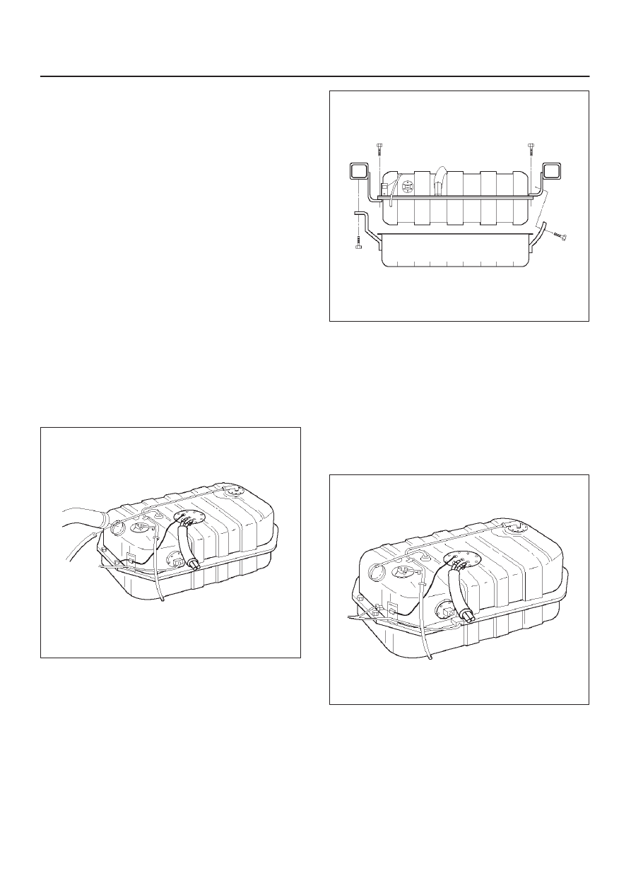
7. Remove the undercover retaining bolts.
8. Remove the undercover.

TS23797

9. Disconnect the wiring connector to the fuel pump.
10. Disconnect the wiring connector to the fuel gauge

unit.

11. Remove the fuel gauge unit connector from the

bracket.

12. Disconnect the EVAP vapor hose.
13. Disconnect the fuel supply hose.
14. Disconnect the fuel return hose.

D

Plug the hoses to prevent dust from entering the
hoses.

TS23769

6E–322

ENGINE DRIVEABILITY AND EMISSIONS

15. Remove the fuel tank retaining bolts on both sides.
16. Remove the fuel tank.

TS23770

Installation Procedure

1. Install the fuel tank.

D

Place the flanges on the left and right side of the
tank on the bracket.

2. Install the fuel tank retaining bolts.

Tighten

D

Tighten the fuel tank retaining bolts to 36 N·m (27 lb
ft.).

TS23770

3. Connect the fuel return hose.
4. Connect the fuel supply hose.
5. Connect the EVAP vapor hose.
6. Connect the wiring connector for the fuel gauge unit.
7. Connect the fuel gauge wiring connector to the

bracket.

8. Connect the wiring connector for the fuel pump.

TS23769

9. Install the undercover.
10. Secure the undercover with the retaining bolts.

TS23797

6E–323

ENGINE DRIVEABILITY AND EMISSIONS

11. Connect the fuel filler fuse at the tank.
12. Connect the air breather hose at the tank.

TS23796

13. Fill the fuel tank with fuel.
14. Tighten the fuel filler cap.
15. Connect the negative battery cable.

Throttle Body (TB)

Removal Procedure

1. Disconnect the negative battery cable.
2. Drain the cooling system.  Refer to 

Cooling System.

3. Remove the accelerator cable assembly.  Refer to

Accelerator Cable in Engine Speed Control System..

4. Disconnect the electrical connectors:

D

Throttle position (TP) sensor.

D

Idle air control (IAC) solenoid.

D

Intake air temperature (IAT) sensor.  Refer to
Intake Air Temperature Sensor.

035RW023

5. Disconnect the vacuum hose below the air horn.
6. Remove the intake air duct clamp.
7. Disconnect the intake air duct.
8. Disconnect the coolant lines from the throttle body.
9. Remove the bolts from the common chamber.
10. Remove the throttle body from the common chamber.
11. Remove the gasket from the upper intake manifold.

035RW024

12. Remove the IAC.  Refer to 

Idle Air Control (IAC)

Solenoid.

13. Remove the TP sensor.  Refer to 

Throttle Position

(TP) Sensor.

Inspection Procedure

NOTE: Do not use solvent of any type when you clean the
gasket surfaces on the intake manifold and the throttle
body assembly.  The gasket surfaces and the throttle
body assembly may be damaged as a result.

D

If the throttle body gasket needs to be replaced,
remove any gasket material that may be stuck to the
mating surfaces of the manifold.

D

Do not leave any scratches in the aluminum casting.

Installation Procedure

1. Install the TP sensor.  Refer to 

Throttle Position (TP)

Sensor.

2. Install the IAC.  Refer to 

Idle Air Control (IAC)

Solenoid.

3. Install the gasket on the common chamber.
4. Install the throttle body on the common chamber.

6E–324

ENGINE DRIVEABILITY AND EMISSIONS

5. Secure the gasket and the throttle body with the four

bolts.

D

The vacuum lines must be properly routed under
the throttle body before tightening the mounting
bolts.

Tighten

D

Tighten the throttle body mounting bolts to 24 N·m
(17 lb ft.).

035RW024

6. Install the coolant lines.
7. Connect all the vacuum lines.
8. Install the intake air duct.
9. Tighten the intake air duct clamp.
10. Connect all the electrical connectors:

D

Throttle position (TP) sensor.

D

Idle air control (IAC) solenoid.

D

Intake air temperature (IAT) sensor.  Refer to
Intake Air Temperature Sensor.

035RW023

11. Install the accelerator cable assembly.  Refer to

Accelerator Cable in Engine Speed Control System..

12. Fill the cooling system.  Refer to 

Cooling System.

13. Install the negative battery cable.

Electronic Ignition System

Removal Procedure

1. Disconnect the negative battery cable.
2. Disconnect the electrical connector at the ignition coil.
3. Remove the two screws that secure the ignition coil to

the rocker cover.

014RW108

4. Remove the ignition coil and the spark plug boot from

the spark plug.

D

Twist the ignition coil while pulling it straight up.

014RW091

5. Use the spark plug socket in order to remove the

spark plug from the engine.


Content   ..  2185  2186  2187  2188   ..