Opel Frontera UBS. Manual - part 2137


  Index      Opel     Opel Frontera UBS - service repair manual 1998-2002 year


Search            


Content   ..  2135  2136  2137  2138   ..


Opel Frontera UBS. Manual - part 2137


6E–121

ENGINE DRIVEABILITY AND EMISSIONS

Diagnostic Trouble Code (DTC) P0113 IAT Sensor Circuit High Voltage
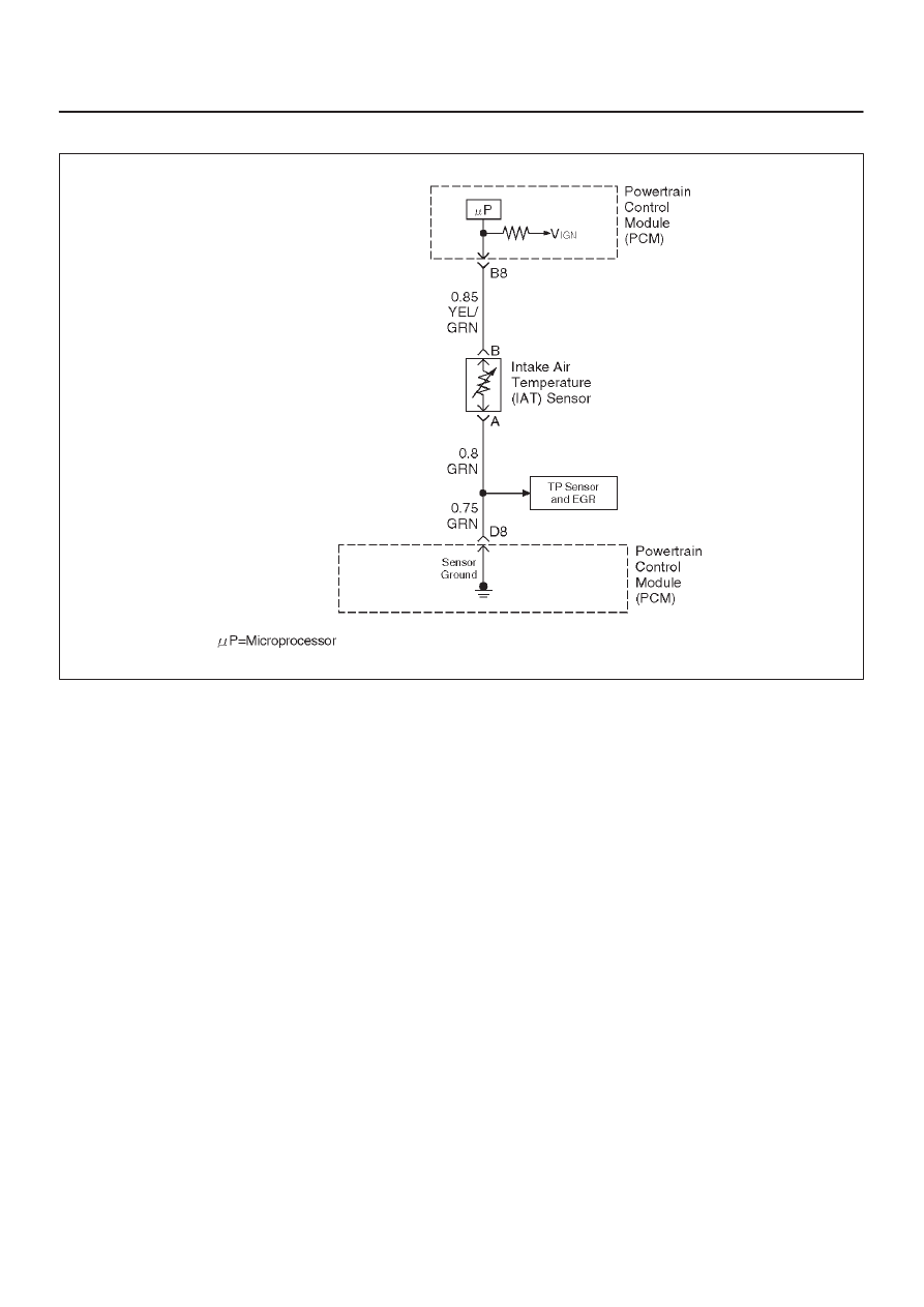
D06RW026

Circuit Description

The intake air temperature (IAT) sensor is a thermistor
which measures the temperature of the air entering the
engine. The powertrain control module (PCM) applies 5
volts through a pull-up resistor to the IAT sensor.  When
the intake air is cold, the sensor resistance is high and the
PCM will monitor a high signal voltage on the IAT signal
circuit.  If the intake air is warm, the sensor resistance is
lower causing the PCM to monitor a lower voltage.  DTC
P0113 will set when the PCM detects an excessively high
signal voltage on the intake air temperature sensor signal
circuit.

Conditions for Setting the DTC

D

The engine has been running for over 4 minutes.

D

Vehicle speed is less than  20 mph (32 km/h). 

D

ECT signal temperature is above 60

°

C (140

°

F).

D

Mass air flow is less then 20 g/second.

D

IAT signal voltage indicates an intake air temperature
less than –39

°

C (–38

°

F) for total of 12.5 seconds over

a 25-second period.

Action Taken When the DTC Sets

D

The PCM will illuminate the malfunction indicator lamp
(MIL) the first time the fault is detected.

D

The PCM will store conditions which were present
when the DTC was set as Freeze Frame and in the
Failure Records data.

Conditions for Clearing the MIL/DTC

D

DTC P0113 can be cleared by using the Tech 2 “Clear
Info” function or by disconnecting the PCM battery
feed.

Diagnostic Aids

Check for the following conditions:

D

The  IAT sensor shares a ground with the EGR position
sensor and the TP sensor.  Check the ground if these
DTC’s are set.

D

Poor connection at PCM – Inspect harness connectors
for backed-out terminals, improper mating, broken
locks, improperly formed or damaged terminals, and
poor terminal-to-wire connection.

D

Damaged harness – Inspect the wiring harness for
damage.  If the harness appears to be OK, observe the
IAT display on the Tech 2 while moving connectors and
wiring harnesses related to the IAT sensor.  A change
in the IAT display will indicate the location of the fault.

If DTC P0113 cannot be duplicated, the information
included in the Failure Records data can be useful in
determining vehicle mileage since the DTC was last set.

Test Description

Number(s) below refer to the step number(s) on the
Diagnostic Chart:
2. Verifies that the fault is present.

6E–122

ENGINE DRIVEABILITY AND EMISSIONS

3. If DTC P0113 can be repeated only by duplicating

the Failure Records conditions, refer to the
“Temperature vs. Resistance Values” table.  The
table may be used to test the IAT sensor at various
temperatures to evaluate the possibility of a
“shifted” sensor that may be open above or below a
certain temperature.  If this is the case, replace the
IAT sensor.  If the IAT sensor appears to be OK, the
fault is intermittent; refer to 

Diagnostic Aids.

Intake Air Temperature Sensor

°

C

°

F

OHMS

Temperature vs. Resistance Values

(approximate)

100

212

177

80

176

332

60

140

667

45

113

1188

35

95

1802

25

77

2796

15

59

4450

5

41

7280

–5

23

12300

–15

5

21450

–30

–22

52700

–40

–40

100700

DTC P0113 –IAT Sensor Circuit High Voltage


Step

Action

Value(s)

Yes

No

1

Was the “On-Board Diagnostic (OBD) System Check”
performed?

Go to 

Step 2

Go to 

OBD

System

Check

2

Ignition “ON,” engine “OFF.”  Observe the “Intake Air
Temp” display on the Tech 2.

Is the “Intake Air Temp” below the specified value?

–38

°

C

(–36

°

F)

Go to 

Step 4

Go to 

Step 3

3

1. Ignition “ON,” engine “OFF.”
2. Review and record Tech 2 Failure Records data

parameters.

3. Operate the vehicle within Failure Records

conditions as noted.

4. Using a Tech 2, monitor “Specific DTC” info for DTC

P0113.

Does the Tech 2 indicate DTC P0113 failed?

Refer to 

Test

Description

Refer to

Diagnostic

Aids

4

1. Ignition “OFF.”
2. Disconnect the IAT sensor electrical connector.
3. Jumper the IAT signal circuit and the sensor ground

circuit together at the IAT sensor harness
connector.

4. Ignition “ON.”
5. Observe the “Intake Air Temp” display on the Tech

2.

Is the “Intake Air Temp” at the specified value?

140

°

C

(284

°

F)

Go to 

Step 6

Go to 

Step 5

5

1. Jumper the IAT signal circuit at the IAT sensor

harness connector to chassis ground.

2. Observe the “Intake Air Temp” display on the Tech

2.

Is the “Intake Air Temp” at the specified value?

140

°

C

(284

°

F)

Go to 

Step 7

Go to 

Step 8

6E–123

ENGINE DRIVEABILITY AND EMISSIONS

DTC P0113 –IAT Sensor Circuit High Voltage

  (Cont'd)

Step

No

Yes

Value(s)

Action

6

Check for poor connections at the IAT sensor and
replace terminals if necessary.

Did any terminals require replacement?

Verify repair

Go to 

Step 10

7

1. Ignition “OFF.”
2. Disconnect the PCM, and check the IAT sensor

ground circuit for an open.

3. If the IAT sensor ground circuit is open, repair it as

necessary.

Was the IAT sensor ground circuit open?

Verify repair

Go to 

Step 9

8

1. Ignition “OFF.”
2. Disconnect the PCM, and check the IAT signal

circuit for an open.

3. If the IAT sensor signal circuit is open, repair it as

necessary.

Was the IAT signal circuit open?

Verify repair

Go to 

Step 9

9

Check for a poor sensor ground or IAT signal circuit
terminal connection at the PCM and replace
terminal(s) if necessary.

Did any of the terminals need to be replaced?

Verify repair

Go to 

Step 11

10

Replace the IAT sensor.

Is the action complete?

Verify repair

11

Replace the PCM.

IMPORTANT: The replacement PCM must be
programmed.  Refer to 

UBS 98model year Immobilizer

Workshop Manual.

Is the action complete?

Verify repair

6E–124

ENGINE DRIVEABILITY AND EMISSIONS

Diagnostic Trouble Code (DTC) P0117 ECT Sensor Circuit Low Voltage

060RY00304

Circuit Description

The engine coolant temperature (ETC) sensor is a
thermistor mounted  on a coolant crossover pipe at the
rear of the engine.  The powertrain control module (PCM)
applies a voltage (about 5 volts) through a pull-up resistor
to the ECT signal circuit.  When the engine coolant is cold,
the sensor (thermistor) resistance is high, therefore the
PCM will measure a high signal voltage.  As the engine
coolant warms, the sensor resistance becomes lower,
and the ECT signal voltage measured at the PCM drops.
With a fully warmed-up engine, the ECT signal voltage
should measure about 1.5 to 2.0 volts.

Conditions for Setting the DTC

D

Engine running time is longer than one minute.

D

The ECT sensor signal indicates an engine coolant
temperature greater than 150

°

C (302

°

F) (about 0.10

V) for a total of 50 seconds over a 100–second period.

Action Taken When the DTC Sets

D

The PCM will illuminate the malfunction indicator lamp
(MIL) the first time the fault is detected.

D

The PCM will substitute the ECT reading with a default
engine coolant temperature value.  The default value
is based on start-up intake air temperature and running
time.

D

The PCM will store conditions which were present
when the DTC was set as Freeze Frame and in the
Failure Records data.

Conditions for Clearing the MIL/DTC

D

DTC P0117 can be cleared by using the Tech 2 “Clear
Info” function or by disconnecting the PCM battery
feed.

Diagnostic Aids

Check for the following conditions:

D

Poor connection at PCM – Inspect harness connectors
for backed-out terminals, improper mating, broken
locks, improperly formed or damaged terminals, and
poor terminal-to-wire connection.

D

Damaged harness – Inspect the wiring harness for
damage.  If the harness appears to be OK, observe the
ECT display on the Tech 2 while moving connectors
and wiring harnesses related to the ECT sensor.  A
change in the ECT display will indicate the location of
the fault.

If DTC P0117 cannot be duplicated, the information
included in the Failure Records data can be useful in
determining vehicle mileage since the DTC was last set.

Test Description

Number(s) below refer to the step number(s) on the
Diagnostic Chart.


Content   ..  2135  2136  2137  2138   ..