Content .. 2111 2112 2113 2114 ..
Opel Frontera UBS. Manual - part 2113
6E–25
ENGINE DRIVEABILITY AND EMISSIONS
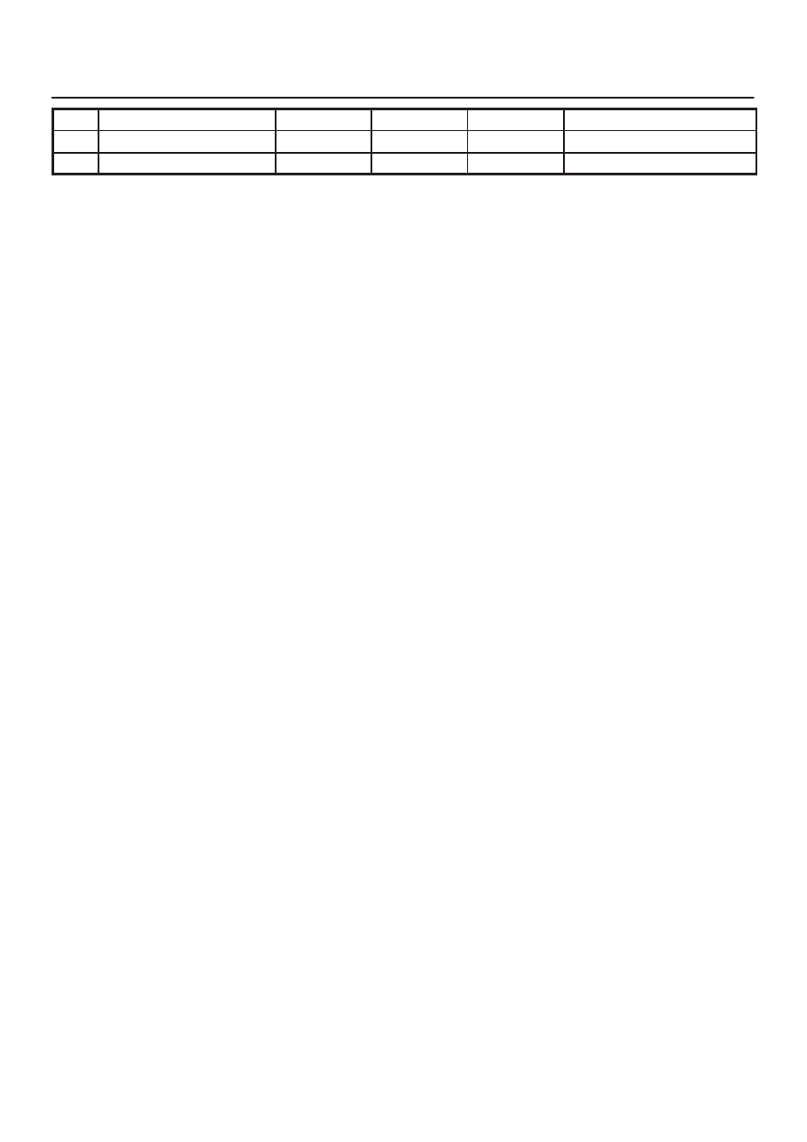
PIN
Refer To
ENG RUN
IGN ON
Wire Color
PIN Function
E15
A/C Request
GRN/ORN
0.0 V
0.0 V
Electric Cooling Fans
E16
Ignition Feed (1 of 2 F16)
RED/BLU
B+
B+
—