Content .. 2103 2104 2105 2106 ..
Opel Frontera UBS. Manual - part 2105

6D3–19
STARTING AND CHARGING SYSTEM
Generator
Removal
1. Disconnect battery ground cable.
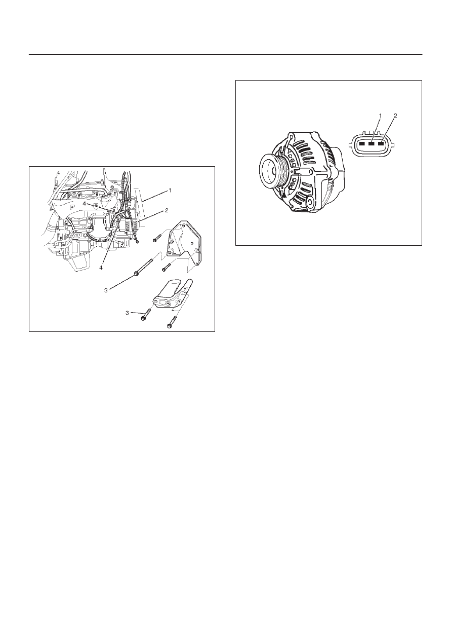
2. Move drive belt tensioner to loose side using wrench
then remove drive belt (1).
3. Disconnect the wire from terminal “B” and disconnect
the connector (4).
4. Remove generator fixing bolt (3).
5. Remove generator assembly (2).
060RW002
Inspection
1. Disconnect the wiring connector from generator.
2. With the engine stopped, turn starter switch to “ON”
and connect a voltmeter between connector terminal
L (2) and ground or between terminal IG (1) and
ground.
066RW001
If voltage is not present, the line between battery and
connector is disconnected and so requires repair.
3. Reconnect the wiring connector to the generator, run
the engine at middle speed, and turn off all electrical
devices other than engine.
4. Measure battery voltage. If it exceeds 16V, repair or
replace the generator.
5. Connect an ammeter to output terminal of generator,
and measure output current under load by turning on
the other electrical devices (eg., head lights). At this
time, the voltage must not be less than 13V.
Installation
1. Install generator assembly to the position to be
installed.
2. Install generator assembly and tighten the fixing bolts
to the specified torque.
Torque:
M10 bolt: 41 N·m (4.2 Kg·m/30 lb ft)
M8 bolt: 21 N·m (2.1 Kg·m/15 lb ft)
3. Connect wiring harness connector and direct terminal
“B”.
4. Move drive belt tensioner to loose side using wrench,
then install drive belt to normal position.
5. Reconnect battery ground cable.