Content .. 2101 2102 2103 2104 ..
Opel Frontera UBS. Manual - part 2103
6D3–11
STARTING AND CHARGING SYSTEM
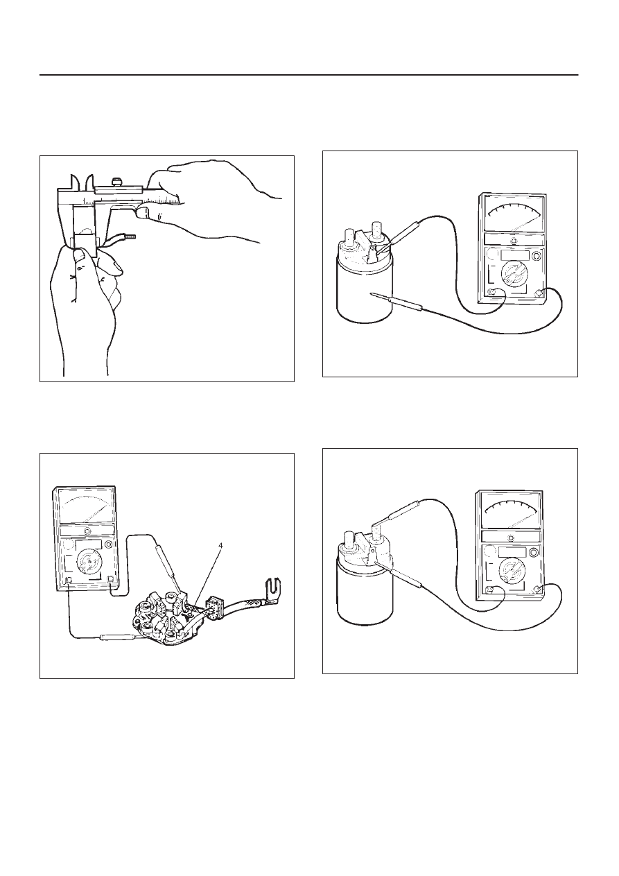
Brush
Measure the length of brush.
Replace with a new one, if it is below the limit.
Standard: 16 mm (0.63 in)
Limit: 11 mm (0.43 in)
065RW014
Brush Holder
Check for continuity between brush holder (+) (4) and
base (–). Replace, if there is continuity (i.e., insulation is
broken).
065RW015
Magnetic Switch
Check for continuity of shunt coil between terminals S and
M.
Replace, if there is no continuity (i.e., coil is
disconnected).
065RW016
Continuity of Series Coil
Check for continuity between terminals S and M.
Replace, if there is no continuity (i.e., coil is
disconnected).
065RW017