Opel Frontera UBS. Manual - part 2053


  Index      Opel     Opel Frontera UBS - service repair manual 1998-2002 year


Search            


Content   ..  2051  2052  2053  2054   ..


Opel Frontera UBS. Manual - part 2053


5C – 24 POWER ASSISTED BRAKE SYSTEM

DISC BRAKES

The disc brake assembly consists of a caliper, piston, rotor, pad assembly and support bracket.  The
caliper assembly has a single bore and is mounted to the support bracket with 2 mounting bolts.  The
support bracket allows the caliper to move laterally against the rotor.  The caliper is a one-piece casting
with the inboard side containing the piston bore.  A square cut rubber seal is located in a groove in the
piston bore which provides the hydraulic seal between the piston and the cylinder wall.

NOTE:
1) Replace all components included in repair kits used to service this caliper.
2) Lubricate rubber parts with clean brake fluid to ease assembly.
3) If any hydraulic component is removed or disconnected, it may be necessary to bleed all or part of

the brake system.

4) Replace pads in axle sets only.
5) The torque values specified are for dry, unlubricated fasteners.
6) Perform service operation a clean bench free from all mineral oil materials.

OPERATION

Hydraulic pressure, created by applying the brake pedal, is converted by the caliper to a stopping force.
This force acts equally against the piston and the bottom of the caliper bore to move the piston outward
and to move (slide) the caliper inward resulting in a clamping action on the rotor.  This clamping action
forces the linings against the rotor, creating friction to stop the vehicle.
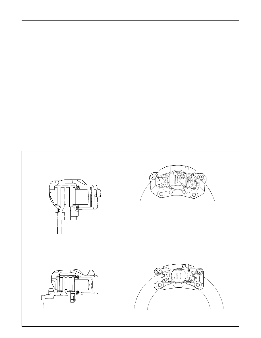
Front disc brakes

Rear disc brakes

POWER ASSISTED BRAKE SYSTEM  5C – 25

ON-VEHICLE SERVICE

BRAKE HOSE REPLACEMENT

1

2

4

2

3

1

2

4

5

3

Front/Rear Caliper Brake Hose

Removal Steps

1.

Brake pipe

2.

Clip 

3.

Bolt and gasket

4.

Hose

Installation Steps

To install, follow the removal steps in the
reverse order.

Rear Axle Brake Hose

Removal Steps

1.

Brake pipe

2.

Clip 

3.

Brake pipe

4.

Bolt

5.

Hose

Installation Steps

To install, follow the removal steps in the
reverse order.

5C – 26 POWER ASSISTED BRAKE SYSTEM

REMOVAL

Preparation:

1) Raise the vehicle and support it with suitable

safety stands.

2) Remove wheel and tire assembly.
3) Clean dirt, grease, and other foreign material off

the hose fittings at both ends.

Front/Rear Caliper Brake Hose

1. Brake Pipe

2. Clip

3. Bolt and Gasket

4. Hose

Rear Axle Brake Hose

1. Brake Pipe

2. Clip

3. Brake Pipe

4. Bolt

5. Hose

INSTALLATION

To install, follow the removal steps in the reverse
order, noting the following points. After installing the
brake hoses, bleed brakes as described in this
section.

Front/Rear Caliper Brake Hose
1. Tighten the brake pipes to the specified torque.

Brake Pipe Torque

N·m(kg·m/lb·ft)

16 (1.6 / 12)

2. Tighten the bolt to the specified torque.

Bolt Torque

N·m(kg·m/lb·ft)

35 (3.5 / 26)

NOTE:

Always use new copper gaskets.

Be sure to put the hooked edge of the flexible
hose end into the anti-rotation cavity.

Rear Axle Brake Hose
1. Tighten the brake pipes to the specified torque.

Brake Pipe Torque

N·m(kg·m/lb·ft)

16 (1.6 / 12)

2. Tighten the bolt to the specified torque.

Bolt Torque

N·m(kg·cm/lb·in)

13 (130 / 113)

POWER ASSISTED BRAKE SYSTEM  5C – 27

BRAKE PIPE REPLACEMENT

1

1

2

Removal Steps

1.

Brake pipe

2.

Plastic clip

Installation Steps

To install, follow the removal steps in the
reverse order.

REMOVAL

Preparation:

1) Raise the vehicle and support it with suitable

safety stands.

2) Remove wheel and tire assembly as necessary.
3) Clean dirt, grease, and other foreign material off

the pipe fittings at both ends.

1. Brake Pipe

2. Plastic Clip

1

Vehice with  LSPV


Content   ..  2051  2052  2053  2054   ..