Index Opel Opel Frontera UBS - service repair manual 1998-2002 year
Search
Content .. 2017 2018 2019 2020 ..
Opel Frontera UBS. Manual - part 2019
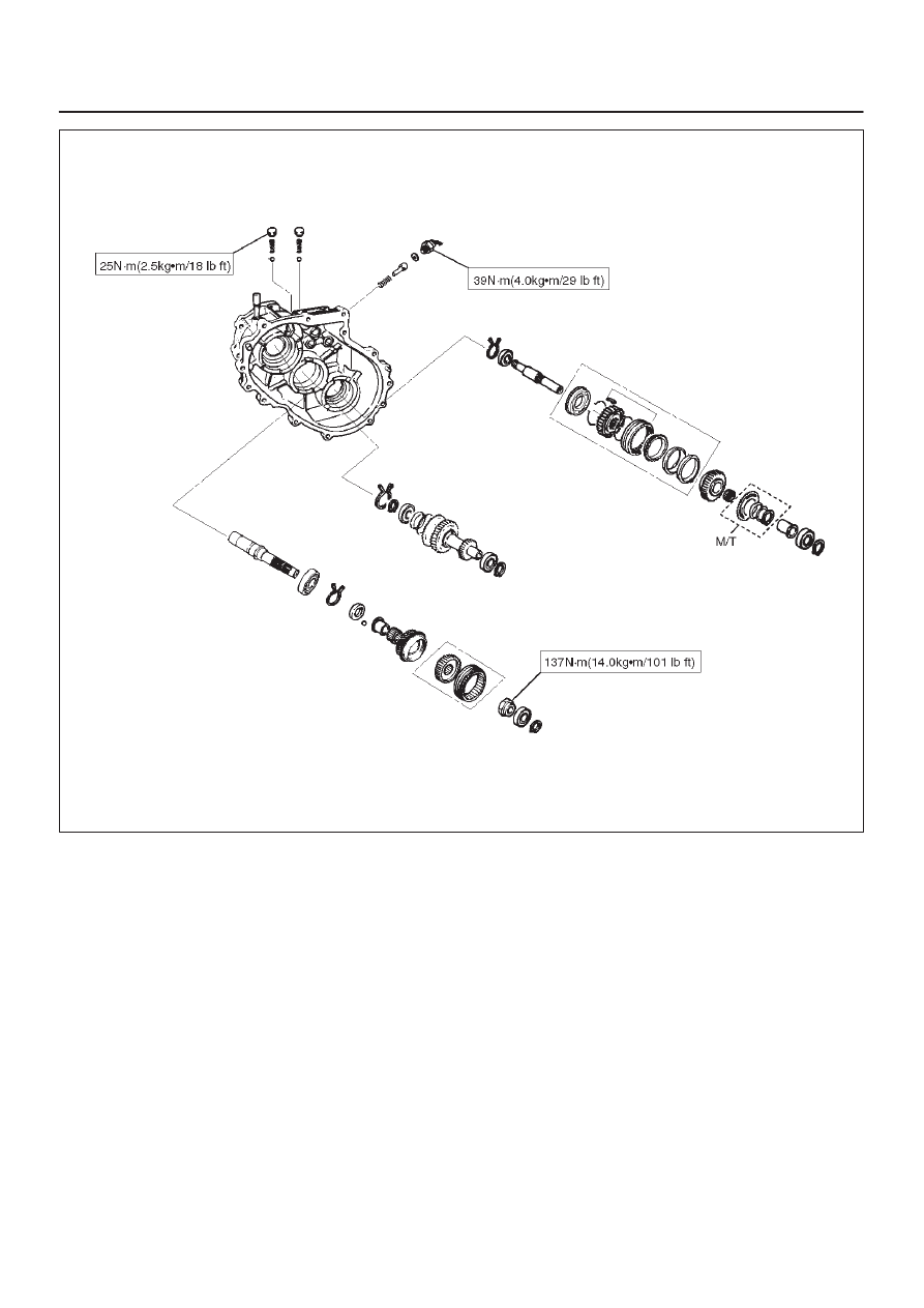
TRANSFER CASE (STANDARD TYPE)
4D1–45
E07RW038