Content .. 2000 2001 2002 2003 ..
Opel Frontera UBS. Manual - part 2002
4C–32
DRIVE SHAFT SYSTEM
Actuator
Check and see that there is no damage, cracking, or other
abnormality.
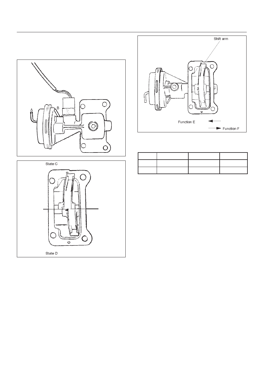
Functional Check
412RW021
412RW013
412RW007
Disconnect the shift position switch and make sure of
function with a vacuum of –400 mmHg applied to Ports A
and B, in accordance with the table below.
State
Port A
Port B
Function
C
–400 mmHg
A/P
E
D
A/P
–400 mmHg
F
If there is an abnormality, replace the actuator as an
assembly.
NOTE:
1. If the actuator works under –400mmHg or less, there
is no functional problem.
2. Be careful not to permit the entry of water or dust into
the ports of the actuator.
Dimensional Check
Measure illustrated sizes 1, 2, and 3.
Limit
1=64.3 mm (2.53 in) max.
2=6.7 mm (0.26 in) min.
3=6.7 mm (0.26 in) min.