Content .. 1971 1972 1973 1974 ..
Opel Frontera UBS. Manual - part 1973
4B2–39
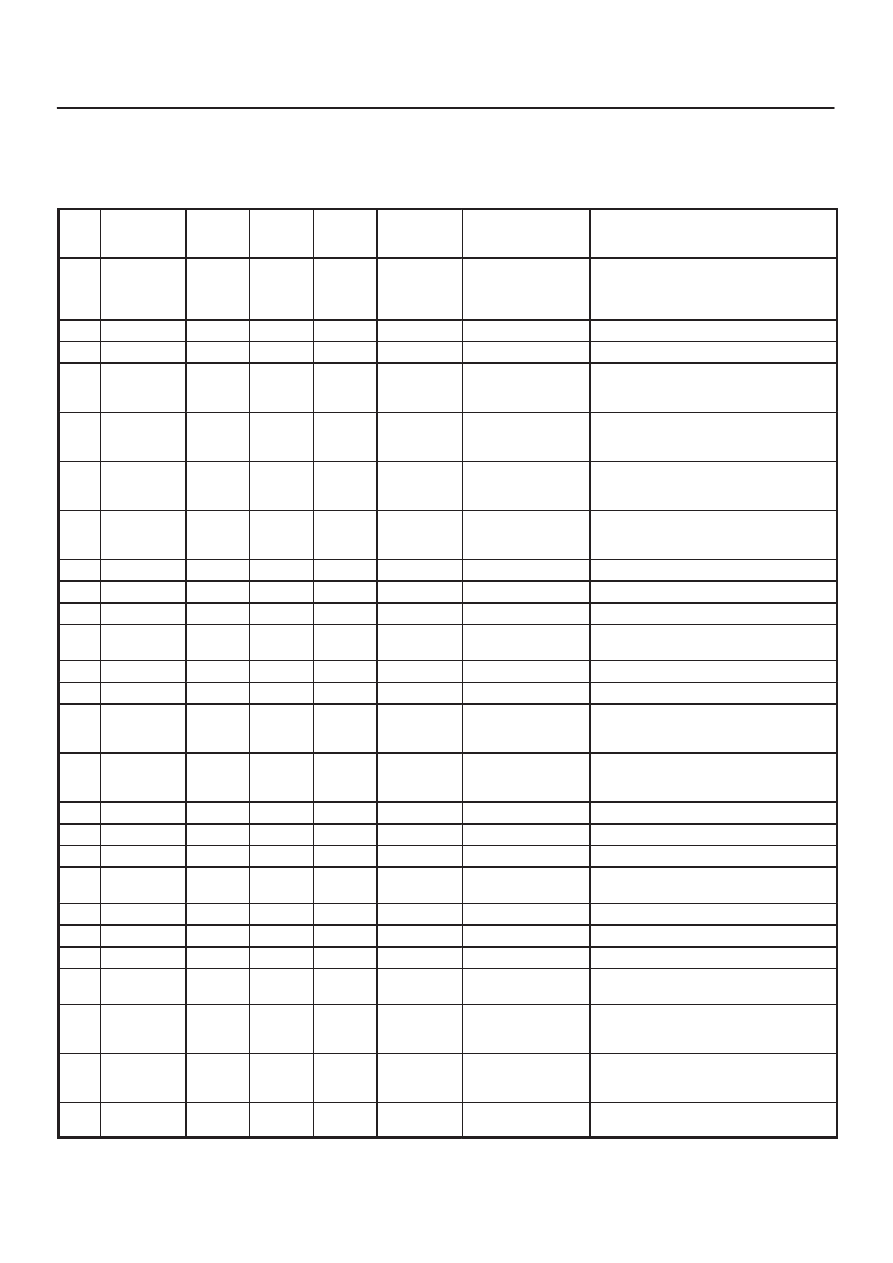
DRIVE LINE CONTROL SYSTEM (TOD)
Checking Failed TOD Control Unit Pin
NOTE:
1. Unplug the ECU connector and the pins, unless
otherwise specified.
2. Before removing the ECU, turn off the ignition switch.
3. If the standard values are not observed, check the
pins with other testers.
Check
Pin
No.
Circuit to be
tested
Ignition
Switch
Position
Engine
State
Multimeter
Scale/
Range
Measure
between Pin
Number
Standard Valve
Note
14
D-G MAP
OFF
STOP
W
14, 19
Continuity : OK
(Gasoline)
No continuity : OK
(Diesel)
20
P-GND
OFF
STOP
W
20, 19
Continuity : OK
19
GND
OFF
STOP
W
19, GND
Continuity : OK
8
4H SW
OFF
STOP
W
8, 19
No continuity (high,
4L) and continuity
(N) : OK
9
4L SW
OFF
STOP
W
9, 19
No continuity (high)
and continuity (4L,
N) : OK
10
AXLE SW
ON
RUN
W
10, 19
Continuity : OK
Remove ECU and start the engine. Move
the vehicle forth and back to connect axle
surely.
13
DIAG
OFF
STOP
W
13 (TOD), 8
(DLC
Connector)
Continuity : OK
DLC connector terminal 8
25
IND.a
ON
STOP
DCV
25 (+), 19 (–)
8.0
∼
14.5 V
When the indicator lamp is turned off.
26
IND.b
ON
STOP
DCV
26 (+), 19 (–)
8.0
∼
14.5 V
When the indicator lamp is turned off.
27
IND.c
ON
STOP
DCV
27 (+), 19 (–)
8.0
∼
14.5 V
When the indicator lamp is turned off.
30
CHECK
LAMP
ON
STOP
DCV
30 (+), 19 (–)
8.0
∼
14.5 V
When the indicator lamp is turned off.
11
ABS IN
ON
STOP
DCV
11 (+), 19 (–)
11.5
∼
14.5 V
15
Ref.
ON
STOP
DCV
15 (+), 19 (–)
5
∼
9 V
Connect ECU
24
Ft.(+)
ON
STOP
DCV
24 (+), 19 (–)
0.7
∼
6 V
Connect ECU (off one tooth of speed
sensor ring) and move the vehicle making
sure of voltage change.
23
Rr.(+)
ON
STOP
DCV
23 (+), 19 (–)
0.7
∼
6 V
Connect ECU (off one tooth of speed
sensor ring) and move the vehicle making
sure of voltage change.
18
COM(-)
ON
STOP
DCV
18 (+), 19 (–)
0V
Connect ECU
1
Vig
ON
STOP
DCV
1 (+), 19 (–)
8
∼
14.5 V
7
BRAKE
OFF
STOP
DCV
7 (+), 19 (–)
8
∼
14.5 V
Press brake pedal
21
TPS
ON
STOP
DCV
21 (+), 19 (–)
0.2
∼
4.6 V
Step on the accelerator pedal and make
sure that voltage changes.
3
4WD OUT
OFF
STOP
W
3, 19
7
∼
12 k
W
Disconnect battery GND terminal
5
ADC(+)
OFF
STOP
W
5, 19
10
∼
30
W
Disconnect battery GND terminal
4
SOL(+)
OFF
STOP
W
4, 19
1.0
∼
5.0
W
Disconnect battery GND terminal
12
4WD SW
ON
STOP
DCV
12 (+), 19 (–)
SW OFF : 0 V
SW ON : 8.0
∼
14.5 V
SW OFF : Contact point open
SW ON : Contact point close
6
LIGHTING
ON
STOP
DCV
6 (+), 19 (–)
SW OFF : 8.0
∼
14.5
V
SW ON : 0 V
28
AUTO INDI
ON
STOP
DCV
28 (+), 19 (–)
TOD : 0 V
2H & 4L : 8.0
∼
14.5
V
Connect ECU
29
RR INDI
ON
STOP
DCV
29 (+), 19 (–)
0 V
Connect ECU. When the indicator lamp is
turned on.