Content .. 1916 1917 1918 1919 ..
Opel Frontera UBS. Manual - part 1918
FRONT SUSPENSION 3C – 11
REMOVAL
Preparation:
1)
Raise the vehicle and support the frame with suitable
safety stands.
2)
Remove wheel and tire assembly. Refer to “Wheels
and Tires” in section 3E.
3)
Remove the brake caliper. Refer to “Brakes” in section
5.
4)
Remove the hub assembly. Refer to “Hub and Disk” in
section 4C.
5)
Remove outer track rod from the knuckle. Refer to
“Steering Linkage” in section 2A.
1. Torsion Bar
Loosen torsion bar by height control arm adjust bolt.
Refer to “Torsion bar” in this section.
2. Wheel speed sensor (if equipped with ABS)
3. Back Plate
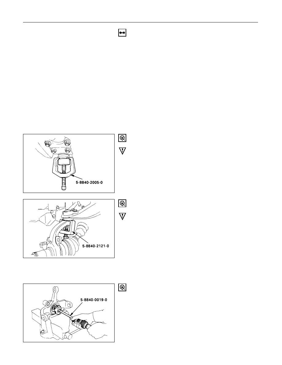
4. Lower Ball Joint
Remover: 5-8840-2005-0 (J-29107)
CAUTION:
Be careful not to break the ball joint boot.
5. Upper Ball Joint
Remover: 5-8840-2121-0 (J-36831)
CAUTION:
Be careful not to break the ball joint boot.
6. Knuckle Assembly
7. Oil Seal
8. Washer
9. Needle Bearing
Remover: 5-8840-0019-0 (J-23907)