Content .. 1797 1798 1799 1800 ..
Opel Frontera UBS. Manual - part 1799
SUPPLEMENTAL RESTRAINT SYSTEM
9J–26
Special Tools
WARNING: TO AVOID DEPLOYMENT WHEN
TROUBLESHOOTING THE SRS, DO NOT USE
ELECTRICAL TEST EQUIPMENT SUCH AS A
BATTERY–POWERED OR AC–POWERED
VOLTMETER, OHMMETER, ETC., OR ANY TYPE OF
ELECTRICAL EQUIPMENT OTHER THAN THAT
SPECIFIED IN THIS MANUAL. DO NOT USE A
NONPOWERED PROBE–TYPE TESTER.
INSTRUCTIONS IN THIS MANUAL MUST BE
FOLLOWED CAREFULLY, OTHERWISE PERSONAL
INJURY MAY RESULT.
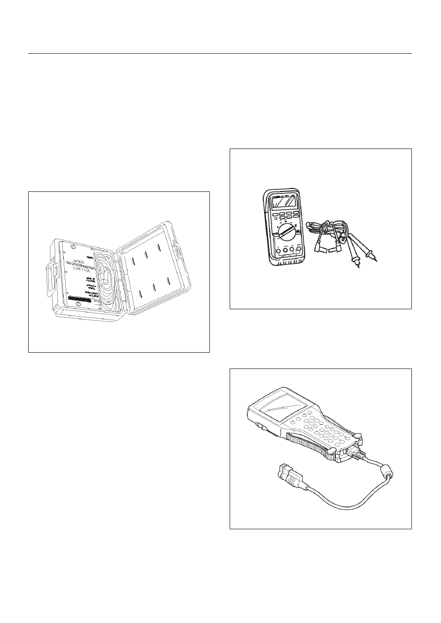
5–8840–2421–0 SRS Driver/Passenger
Load Tool
901RS146
The SRS Driver/Passenger Load Tool 5–8840–2421–0 is
used only when called for in this section. It is used as a
diagnostic aid and safety device to prevent inadvertent air
bag assembly deployment.
The load tool has three yellow connectors attached to its
case.
The three small connectors are electrically functional and
serve as resistive load substitutions.
No more than two connectors are used at any time. One
of the small connectors is used to substitute for the load of
the driver air bag assembly when it is connected at the top
of the column to the SRS coil assembly. Another small
connector is used to substitute for the load of the driver air
bag assembly and the SRS coil assembly when it is
connected at the base of the column to the SRS wiring
harness. The third small connector is used to substitute
for the load of the passenger air bag assembly and
pretensioner seat belt assembly when connected to the
passenger air bag assembly and pretensioner seat belt
assembly harness connector.
By substituting the resistance of the load tool when called
for, a determination can be made as to whether an inflator
circuit component is causing system malfunction and
which component is causing the malfunction. The load
tool should be used only when specifically called for in the
diagnostic procedures.
NOTE: If comand to use 5–8840–2421–0 load tool when
repair the pretensioner seat belt, connect load tool
connector to use for driver air bag and/or passenger air
bag connector.
5–8840–0285–0 DVM
901RS153
The 5–8840–0285–0 DVM is the preferred DVM for use in
SRS diagnosis and repair. However, 5–8840–0366–0
may be used if 5–8840–0285–0 is not available. No other
DVMs are approved for SRS diagnosis and repair.
Scan Tool
901RW176
The Tech 2 is used to read and clear SRS Diagnostic
Trouble Codes (DTCs). Refer to the Tech 2 Operators,
Manual for specific information on how to use the Tech 2.