Content .. 1759 1760 1761 1762 ..
Opel Frontera UBS. Manual - part 1761
8F–115
BODY STRUCTURE
Special Tools
ILLUSTRATION
TOOL NO.
TOOL NAME
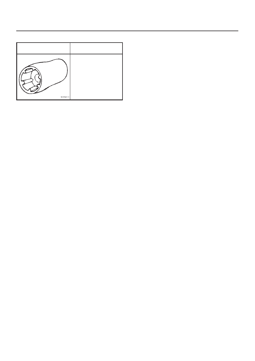
5–8840–2095–0
(J–34355)
Spare Tire Carrior Bolt
Wrench
|
|
|
Content .. 1759 1760 1761 1762 ..
8F–115 BODY STRUCTURE Special Tools ILLUSTRATION TOOL NO. TOOL NAME 5–8840–2095–0 (J–34355) Spare Tire Carrior Bolt Wrench |