Opel Frontera UBS. Manual - part 1735


  Index      Opel     Opel Frontera UBS - service repair manual 1998-2002 year


Search            


Content   ..  1733  1734  1735  1736   ..


Opel Frontera UBS. Manual - part 1735


8F–11

BODY STRUCTURE

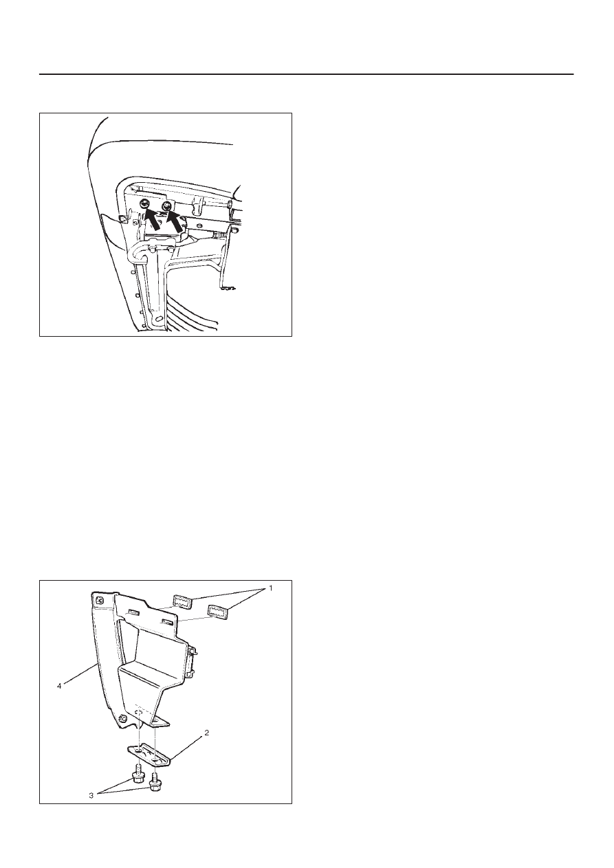
5. Remove rear bumper assembly fixing bolts.

D

Remove two bolts from each side.

690RW002

6. Remove rear bumper assembly.
7. Remove rear bumper retainers.
8. Remove rear combination light back plate.
9. Remove reinforce upper bolts.

D

Remove the rear bumper retainer from each side,
and then remove two upper bolts.

10. Remove reinforce lower screws.

11. Remove rear step clips.

12. Remove rear step.
13. Remove reinforce assembly.

D

Pull out both ends of the bumper fascia and take out
the reinforce assembly.

14. Remove backbars.

D

Remove the three bolts from each backbar.

15. Remove rear bumper slider brackets(4).

D

Remove the two clips(1) and two screws(3), and
then remove claw caught in the washer(2).

690RS003

16. Remove bumper fascia brackets.

D

Remove the fixing nut on the back side of the fender
panel.

17. Remove rear combination light assembly.
18. Remove license light.

Installation

To install, follow the removal steps in reverse order noting
the following points:

1. Tighten the rear bumper assembly fixing bolts to the

specified torque.

Torque: 132 N

m (13.5kg·m/98 lb ft)

2. Apply chassis grease to the slider and the slider

bracket moving surface.

8F–12

BODY STRUCTURE

Rear Bumper Slider

Removal

1. Remove the rear bumper.

D

Refer to Rear Bumper removal in this section.

2. Remove the three bolts (2).
3. Remove rear bumper slider (1).

690RS004

Installation

To install, follow the removal steps in reverse order noting
the following points:

1. Apply chassis grease to the slider and the slider

bracket moving surface.

8F–13

BODY STRUCTURE

General Description

This section includes items of front end sheet metal that
are attached by bolts, screws or clips and related
accessory components.

Anti-corrosion materials have been applied to the interior
surfaces of some metal panels to provide rust resistance.
When servicing these panels, areas on which this
material has been disturbed should be properly recoated
with service-type anti-corrosion material.

Cowl Cover

Parts Location

605RW009

Legend

(1) Front Wiper Arms
(2) Cowl Cover
(3) Cowl Cover Brackets

(4) Cowl Cover Stoppers
(5) Cowl Cover Seals
(6) Front Window Lower Molding

Removal

1. Open the hood.
2. Support the hood.

3. Remove front wiper arms.

D

Refer to Windshield Wiper Arm/Blade in
Wiper/Washer System section.

8F–14

BODY STRUCTURE

4. Remove cowl cover brackets.

D

Disconnect two screws each side.

5. Remove cowl cover.

D

Disconnect three screws.

6. Remove cowl cover seals.

7. Remove front window lower molding.
8. Remove cowl cover stoppers.

Installation

To install, follow the removal steps in reverse order.

Engine Hood

Removal

1. Open the hood.
2. Support the hood.
3. Remove windowshield washer nozzle tube.

880RS001

4. Remove hood hinge bolts (3).

D

Before removing the hinges from the engine hood
(1), scribe a mark (2) showing location of the hinges
to facilitate installation in the original position.

610RS003

5. Remove engine hood.

Installation

To install, follow the removal steps in the reverse order
noting the following points:

1. Tighten the engine hood fixing bolts to the specified

torque.

Torque: 13 N

m (1.3kg·m/113 lb in)

2. Adjust the engine hood mounting gap with reference

to Body Dimension in this section.

3. Check and see if the engine hood lock operates

normally.


Content   ..  1733  1734  1735  1736   ..