Opel Frontera UBS. Manual - part 1731


  Index      Opel     Opel Frontera UBS - service repair manual 1998-2002 year


Search            


Content   ..  1729  1730  1731  1732   ..


Opel Frontera UBS. Manual - part 1731


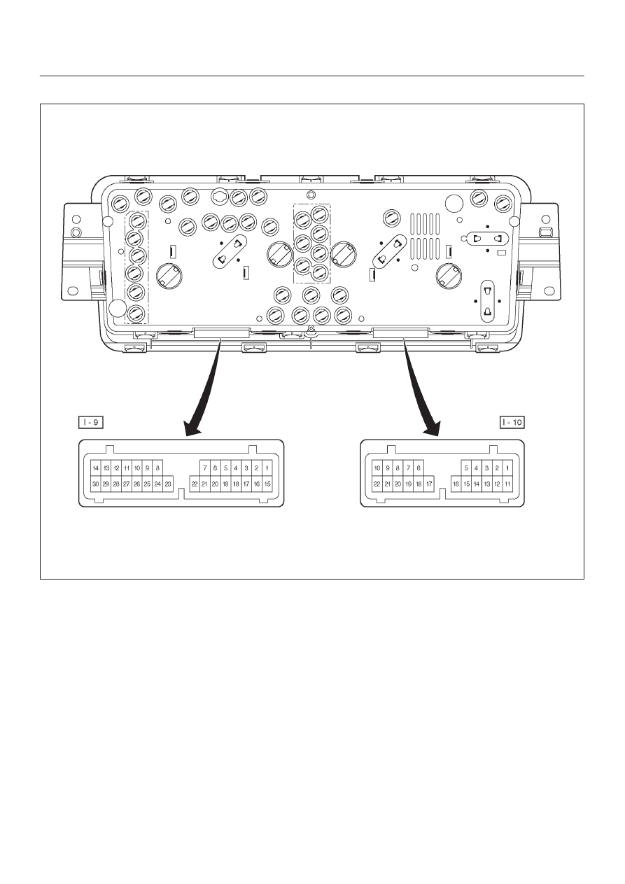
8E–14 METER AND GAUGE

Meter Assembly–Diesel W/TOD–1

821R200052

METER AND GAUGE

8E–15

Meter Assembly–Diesel W/TOD–2

Connector No. I–9

Terminal

Function

1

2

Air bag warning light

3

A/T oil temp warning light

4

Charge warning light

5

Seat belt warning light
Water sedimenter

6

Check trans warning light

7

Brake warning light

8

9

Tachometer

10

11

Turn signal indicator light (left)

12

13

L position (A/T)

14

D position (A/T)

15

Rear (TOD)

16

Auto (TOD)

17

Check (TOD)

18

19

20

Oil pressure warning light

21

Front “1” (TOD)

22

Front “2” (TOD)

23

Front “3” (TOD)

24

Meter illumination light

25

Illumination controller

26

Starter switch

27

28

Winter drive indicator light

29

Power drive indicator light

30

Glow indicator light

Connector No. I–10

Terminal

Function

1

Turn signal indicator light (Right)

2

O/D OFF position (A/T)

3

R position (A/T)

4

Ground

5

Speedometer

6

7

8

Ground (Gauge)

9

Check engine warning light

10

Battery (+)

11

P position (A/T)

12

N position (A/T)

13

2 position (A/T)

14

High-beam indicator light (–)

15

High-beam indicator light (+)

16

ABS indicator light

17

18

Fuel warning light

19

20

Fuel gauge

21

Rear fog light

22

Engine coolant temperature

8E–16 METER AND GAUGE

Removal

1. Disconnect the battery ground cable.
2. Remove the front console assembly(1).

Refer to the Instrument Panel Assembly in Body
Structure section.

3. Remove the lower cluster assembly(2).

Refer to the Instrument Panel Assembly in Body
Structure section.

4. Remove the instrument panel driver lower cover(3).

Refer to the Instrument Panel Assembly in Body
Structure section.

740RS004

5. Remove four fixing screws and disconnect the meter

connectors to remove the meter assembly(5).

825RW031

CAUTION: The removed meter assembly should be
placed upright or with its face side up.

Installation

To install, follow the removal steps in the reverse order.

Warning Light Bulb, Indicator Light Bulb, Illumination Light Bulb,

A/T Indicator Light Bulb

Removal

1. Disconnect the battery ground cable.
2. Remove the meter assembly(1).

Refer to the Meter Assembly removal steps in this
section.

3. Hold the bulb socket by hand and rotate it

counterclockwise to remove the socket & bulb(2)
from the meter body.

825RW032

Installation

To install, follow the removal steps in the reverse order.

METER AND GAUGE

8E–17

Vehicle Speed Sensor

Removal

1. Disconnect the battery ground cable.
2. Disconnect the connector, remove the vehicle speed

sensor body by rotating it and then remove the vehicle
speed sensor(1).

826RS009

Installation

To install, follow the removal steps in the reverse order,
noting the following point.

1. Tighten the vehicle speed sensor to the specified

torque.

Torque: 27 N·m (2.8 kg·m/20 lb ft)

Fuel Tank Unit

Removal

1. Disconnect the battery ground cable.
2. Remove the fuel tank(1).

Refer to the Fuel Tank removal steps in Engine
section

3. Disconnect the connectors, remove five screws and

then remove the fuel tank unit(2).

140RS006

Installation

To install, follow the removal steps in the reverse order.


Content   ..  1729  1730  1731  1732   ..