Opel Frontera UBS. Manual - part 148
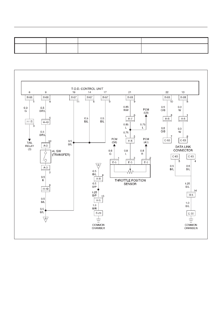
DRIVE LINE CONTROL SYSTEM (TOD)
4B2–44
Check flow
Trouble code
Phenomenon
Standard
8
34
The diesel/gasoline engine identifi-
cation signal is faulty.
Gasoline: Continuity established
The engine identification signals of 6VE1 and 4JX1 are
changed each other.
D04RW056