Opel Frontera UBS. Manual - part 147
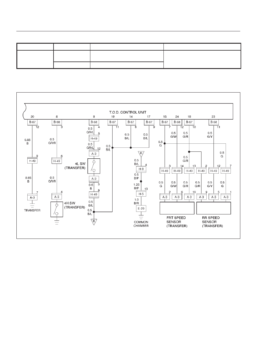
DRIVE LINE CONTROL SYSTEM (TOD)
4B2–40
Check flow
Trouble code
Phenomenon
Standard
6
13
The reference is short-circuited to
GND.
Reference
]
5 V
15
The reference Vb is short-circuited.
If the reference wire (15) is short-circuited to GND, the
speed signal is not generated. If the wire is short-circuited
to the battery voltage, the signal level becomes faulty.
D04RW061