Opel Frontera UBS. Manual - part 1466


  Index      Opel     Opel Frontera UBS - service repair manual 1998-2002 year


Search            


Content   ..  1464  1465  1466  1467   ..


Opel Frontera UBS. Manual - part 1466


7A–106

AUTOMATIC TRANSMISSION (AW30-40LE)

247RY00009

248RY00018

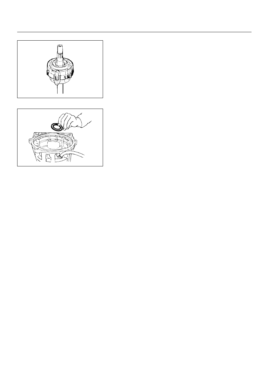
26. Rear planetary gear, second brake drum and output

shaft
Remove the rear planetary gear, second brake drum and
output shaft as an assembly.

27. Bearing

Remove the assembled thrust bearing and race from the
case.

AUTOMATIC TRANSMISSION (AW30-40LE)

7A–107

DISASSEMBLY, INSPECTION AND 
REASSEMBLY OF MINOR COMPONENTS

The instructions here are organized so that you work on only
one component group at a time.
This will help avoid confusion from similar-looking parts of
different subassemblies being on your workbench at the same
time.
The component groups are inspected and repaired from the
converter housing side.
As much as possible, complete the inspection, repair and
reassembly before proceeding to the next component group. If
a component group cannot be reassembled because parts are
being ordered, be sure to keep all parts of that group in a
separate container while proceeding with disassembly,
inspection, repair and reassembly of other component groups.
Recommended ATF type BESCO ATF II or III.

GENERAL CLEANING NOTES:

1. All disassembled parts should be washed clean and any

fluid passages and holes blown through with compressed
air.

2. When using compressed air to dry parts, always aim away

from yourself to prevent accidentally spraying automatic
transmission fluid in your face.

3. The recommended automatic transmission fluid should be

used for cleaning.

PARTS ARRANGEMENT:

1. After cleaning, the parts should be arranged in proper order

to allow performing inspection, repairs, and reassembly
with efficiency.

2. When disassembling a valve body, be sure to keep each

valve together with the corresponding spring.

3. New brakes and clutches that are to be used for

replacement must be soaked in transmission fluid for at
least thirty before assembly.

GENERAL ASSEMBLY:

1. All oil seal rings, clutch discs, clutch plates, rotating parts,

and sliding surfaces should be coated with transmission
fluid prior to reassembly.

2. All gaskets and rubber O-rings should be replaced.

3. Make sure that ends of a snap ring are not aligned with one

of the cutouts and are installed in the groove correctly.

4. If a worn bushing is to be replaced, the subassembly

containing that bushing must be replaced.

5. Check thrust bearings and races for wear or damage.

Replace if necessary.

6. Use petroleum jelly or vaseline to keep parts in place.

7A–108

AUTOMATIC TRANSMISSION (AW30-40LE)

OIL PUMP

DISASSEMBLY

241RY00004

241RY00005

Important operations

1. Oil seal ring

Use torque converter as work stand. 
Remove 2 oil seal rings from stator shaft.

2. O-ring

Remove O-ring.

Disassembly steps

 1. Oil seal ring

 2. O-ring

 3. Stator shaft

 4. Oil pump drive gear

 5. Oil pump driven gear

AUTOMATIC TRANSMISSION (AW30-40LE)

7A–109

241RY00006

241RY00007

241RY00008

3. Stator shaft

Remove 13 bolts, and then remove the stator shaft from oil
pump body.
Then remove drive and driven gear.

INSPECTION AND REPAIR

Make necessary correction or parts replacement if wear,
damage or any abnormal conditions are found through
inspection.

Check oil pump body bushing

Using a dial indicator, measure the inside diameter of the
oil pump body bushing.

If the inside diameter is greater than the maximum, replace
the oil pump body.

Check stator shaft bushing

Using a dial indicator, measure the inside diameter of the stator
shaft bushing.

If the inside diameter is greater than maximum, replace the
stator shaft.

mm (in.)

Maximum inside diameter

38.19 (1.5035)

mm (in.)

Maximum inside 

diameter

Front side

21.58 (0.8496)

Rear side

27.08 (1.0661)


Content   ..  1464  1465  1466  1467   ..