Opel Frontera UBS. Manual - part 1408


  Index      Opel     Opel Frontera UBS - service repair manual 1998-2002 year


Search            


Content   ..  1406  1407  1408  1409   ..


Opel Frontera UBS. Manual - part 1408


6E–226

4JX1–TC ENGINE DRIVEABILITY AND EMISSIONS

0018

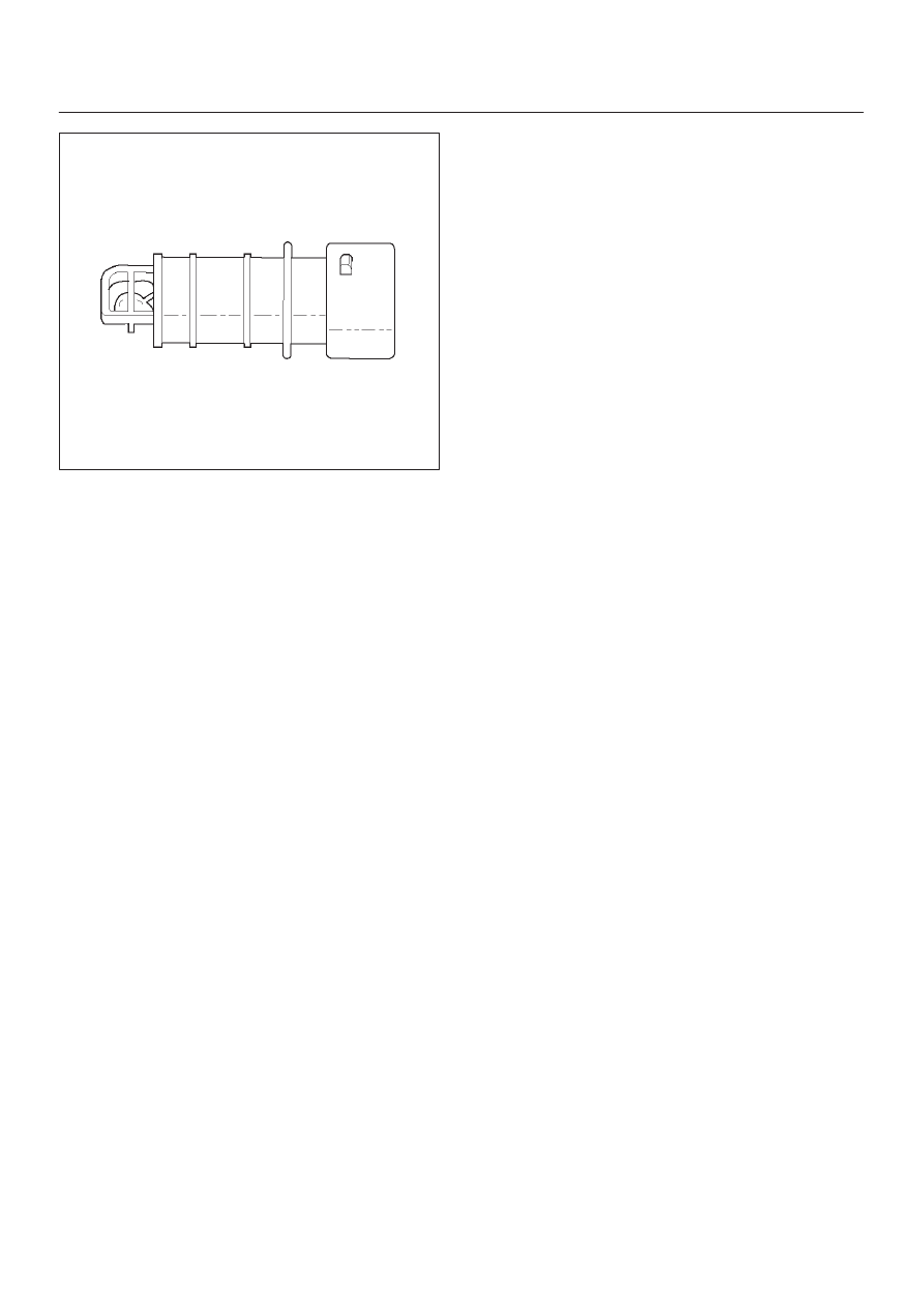
Manifold Absolute Pressure (MAP) Sensor

The manifold absolute pressure (MAP) sensor responds
to changes in intake manifold pressure.  The MAP sensor
signal voltage to the ECM varies from below 2 volts at idle
(high vacuum) to above 4 volts.
The MAP sensor is used to determine the following:

D

Boost pressure for injector control.

D

Barometric pressure (BARO).

If the ECM detects a voltage that is lower than the
possible range of the MAP sensor, DTC P0107 will be set.
A signal voltage higher than the possible range of the
sensor will set DTC P0108.  An intermittent low or high
voltage will set DTC P1107 or DTC P1106, respectively.
The ECM can detect a shifted MAP sensor.  The ECM
compares the MAP sensor signal to a calculated MAP
based on throttle position and various engine load factors.
If the ECM detects a MAP signal that varies excessively
above or below the calculated value, DTC P0106 will set.

Engine Control Module (ECM)

The engine control module (ECM) is located in the engine
room.
The ECM constantly observes the information from
various sensors.  The ECM controls the systems that
affect vehicle performance.  The ECM performs the
diagnostic function of the system.  It can recognize
operational problems, alert the driver through the MIL
(Service Engine Soon lamp), and store diagnostic trouble
codes (DTCs).  DTCs identify the problem areas to aid the
technician in making repairs.

ECM Function

The ECM supplies 5, 12 and 110 volts to power various
sensors or switches.  The power is supplied through
resistances in the ECM which are so high in value that a
test light will not light when connected to the circuit.  In
some cases, even an ordinary shop voltmeter will not give
an accurate reading because its resistance is too low.
Therefore, a digital voltmeter with at least 10 megohms
input impedance is required to ensure accurate voltage
readings. The ECM controls output circuits such as the

injectors, glow relays, etc., by controlling the ground or
the power feed circuit through transistors or through
either of the following two devices:

D

Output Driver Module (ODM)

D

Quad Driver Module (QDM)

ECM Components

The ECM is designed to maintain exhaust emission levels
to government mandated standards while providing
excellent driveability and fuel efficiency.  The ECM
monitors numerous engine and vehicle functions via
electronic sensors such as the crankshaft position (CKP)
sensor, and vehicle speed sensor (VSS).  The ECM also
controls certain engine operations through the following:

D

Fuel injector control

D

Rail pressure control

ECM Voltage Description

The ECM supplies a buffered voltage to various switches
and sensors.  It can do this because resistance in the
ECM is so high in value that a test light may not illuminate
when connected to the circuit.  An ordinary shop
voltmeter may not give an accurate reading because the
voltmeter input impedance is too low.  Use a 10-megohm
input impedance digital voltmeter to assure accurate
voltage readings.
The input/output devices in the ECM include
analog-to-digital converters, signal buffers, counters,
and special drivers.  The ECM controls most components
with electronic switches which complete a ground circuit
when turned “ON.”  These switches are arranged in
groups of 4 and 7, called either a surface-mounted quad
driver module (QDM), which can independently control up
to 4 output terminals, or QDMs which can independently
control up to 7 outputs.  Not all outputs are always used.

ECM Input/Outputs

Inputs – Operating Conditions Read

D

Air Conditioning “ON” or “OFF” 

D

Engine Coolant Temperature

D

Crankshaft Position

D

Electronic Ignition

D

Manifold Absolute Pressure

D

Battery Voltage

D

Intake Throttle Position

D

Vehicle Speed

D

Fuel Temperature

D

Oil Temperature

D

Intake Air Temperature

D

EGR boost pressure

D

Oil rail pressure

D

Camshaft Position

D

Accelerator position

Outputs – Systems Controlled

D

Exhaust Gas Recirculation (EGR)

D

Injector Control

D

QWS

6E–227

4JX1–TC ENGINE DRIVEABILITY AND EMISSIONS

D

QOS

D

Diagnostics

Malfunction Indicator Lamp (Service Engine
Soon lamp)

Data Link Connector (DLC)

Data Output

ECM Service Precautions

The ECM is designed to withstand normal current draws
associated with vehicle operation.  Avoid overloading any
circuit.  When testing for opens and shorts, do not ground
or apply voltage to any of the ECM’s circuits unless
instructed to do so.  These circuits should only be tested
using digital voltmeter. The ECM should remain
connected to the ECM or to a recommended breakout
box.

Intake Throttle Position (ITP) Sensor

ITP sensor is a potentiometer type and installed to the
intake throttle valve body. A voltage of 5V is applied
constantly from ECM to ITP sensor thereby to determine
by change in voltage the opening of the intake throttle
valve during warming up.

Transmission Range Switch

IMPORTANT:

The vehicle should not be driven with the

transmission range switch disconnected; idle quality will
be affected.
The four inputs from the transmission range switch
indicate to the ECM which position is selected by the
transmission selector lever.
For more information on the transmission on the
transmission range switch, refer to 

Automatic

Transmission.

Accelerator Position Sensor (AP)

AP sensor is a potentiometer type and installed to
accelerator pedal bracket. A voltage of 5V constantly
applied from ECM to the sensor thereby to determine the
accelerator pedaling angle by change in voltage. Further,
this sensor is provided with an accelerator switch, which
is set off only when the accelerator pedal is stepped on.

Aftermarket Electrical and Vacuum
Equipment

Aftermarket (add-on) electrical and vacuum equipment is
defined as any equipment which connects to the vehicle’s
electrical or vacuum systems that is installed on a vehicle
after it leaves the factory.  No allowances have been
made in the vehicle design for this type of equipment.

NOTE: No add-on vacuum equipment should be added
to this vehicle.

NOTE: Add-on electrical equipment must only be
connected to the vehicle’s electrical system at the battery
(power and ground).

Add-on electrical equipment, even when installed to
these guidelines, may still cause the powertrain system to
malfunction. This may also include equipment not
connected to the vehicle electrical system such as

portable telephones and radios.  Therefore, the first step
in diagnosing any powertrain problem is to eliminate all
aftermarket electrical equipment from the vehicle.  After
this is done, if the problem still exists, it may be diagnosed
in the normal manner.

Electrostatic Discharge Damage

Electronic components used in the ECM are often
designed to carry very low voltage.  Electronic
components are susceptible to damage caused by
electrostatic discharge.  Less than 100 volts of static
electricity can cause damage to some electronic
components.  By comparison, it takes as much as 4000
volts for a person to feel even the zap of a static
discharge.

TS23793

There are several ways for a person to become statically
charged.  The most common methods of charging are by
friction and induction.

D

An example of charging by friction is a person sliding
across a vehicle seat.

D

Charge by induction occurs when a person with well
insulated shoes stands near a highly charged object
and momentary touches ground.  Charges of the
same polarity are drained off leaving the person
highly charged with the opposite polarity.  Static
charges can cause damage, therefore it is important
to use care when handling and testing electronic
components.

NOTE: To prevent possible electrostatic discharge
damage, follow these guidelines:

D

Do not touch the ECM connector pins or soldered
components on the ECM circuit board.

D

Do not open the replacement part package until the
part is ready to be installed.

D

Before removing the part from the package, ground
the package to a known good ground on the vehicle.

D

If the part has been handled while sliding across the
seat, while sitting down from a standing position, or
while walking a distance, touch a known good ground
before installing the part.

6E–228

4JX1–TC ENGINE DRIVEABILITY AND EMISSIONS

General Description (Air Induction)

Air Induction System

The air induction system filters contaminants from the
outside air, and directs the progress of the air as it is
drawn into the engine.  A remote-mounted air cleaner
prevents dirt and debris in the air from entering the
engine.  The air duct assembly routes filtered air to the
throttle body.  Air enters the engine by to following steps:

1. Through the throttle body.
2. Into the intake manifold.
3. Through the cylinder head intake ports.
4. Into the cylinders.

General Description (Fuel Metering)

Deceleration Mode

The ECM reduces the amount of fuel injected when it
detects a decrease in the Accelerator position.

Fuel Injector

Fuel injector comprises the solenoid, hydraulic line, and
fuel line. Fuel injection is controlled by the continuity time
signal and continuity start timing signal from ECM to the
solenoid
ECM determines the running conditions of engine by
input signals such as engine speed. Accelerator throttle
valve opening, and engine coolant temperature, thereby
to send the solenoid the best suited signal to the engine
status. When current is carried to the solenoid, the
armature opens the poppet valve to alow high pressure oil
to run into the injector. Under the pressure of the oil, the
piston and plunger are depressed to compress the fuel in
the combustion chamber of the plunger. Specifically, the
pressure of the fuel compressed is increased by a piston
top/ plunger bottom area ratio over the pressure of high
pressure oil, thereby lifting the fuel nozzle end needle for
injecting fuel.

Fuel Metering System Components

The fuel metering system is made up of the following
parts:

D

The fuel injectors.

D

The intake throttle body.

D

The Accelerator position (AP) sensor

D

The ECM.

D

The crankshaft position (CKP) sensor.

D

The camshaft position (CMP) sensor.

Basic System Operation
Fuel is supplied through fuel filter to the fuel pump.
The fuel pump is installed to the oil pump, and fuel is
forced, through the fuel pump outlet, pipe and cylinder
head inside, into the fuel injector.
An orifice is provided at the rear fuel outlet of cylinder
head to control the pressure of oil.

The injector is controlled by ECM which gives
opening/closing commands to the solenoid installed on
the top of the injector. Opening/closing operation of the
pressurized engine oil circuit of the injector controls fuel
injection quantity, fuel injection timing, etc.

A/C Clutch Diagnosis

A/C Request Signal

This signal tells the ECM when the A/C mode is selected
at the A/C control head.  The ECM uses this to adjust the
idle speed.
Refer to 

A/C Clutch Circuit Diagnosis for A/C wiring

diagrams and diagnosis for A/C electrical system.

General Description Exhaust Gas

Recirculation (EGR) System

EGR Purpose

The exhaust gas recirculation (EGR) system is use to
reduce emission levels of oxides of nitrogen (NOx).  NOx
emission levels are caused by a high combustion
temperature.  The EGR system lowers the NOx emission
levels by decreasing the combustion temperature.
The ECM uses information from the following sensors to
control EGR valve boost pressure.

D

ECT

D

ITP

D

Engine Speed

D

AP sensor

6E–229

4JX1–TC ENGINE DRIVEABILITY AND EMISSIONS

Fuse and Relay Panel (Underhood Electrical Center) RHD

035RW109


Content   ..  1406  1407  1408  1409   ..