Opel Frontera UBS. Manual - part 1380


  Index      Opel     Opel Frontera UBS - service repair manual 1998-2002 year


Search            


Content   ..  1378  1379  1380  1381   ..


Opel Frontera UBS. Manual - part 1380


6E–114

4JX1–TC ENGINE DRIVEABILITY AND EMISSIONS

Diagnostic Trouble Code (DTC) P0336 (Flash DTC 43) 

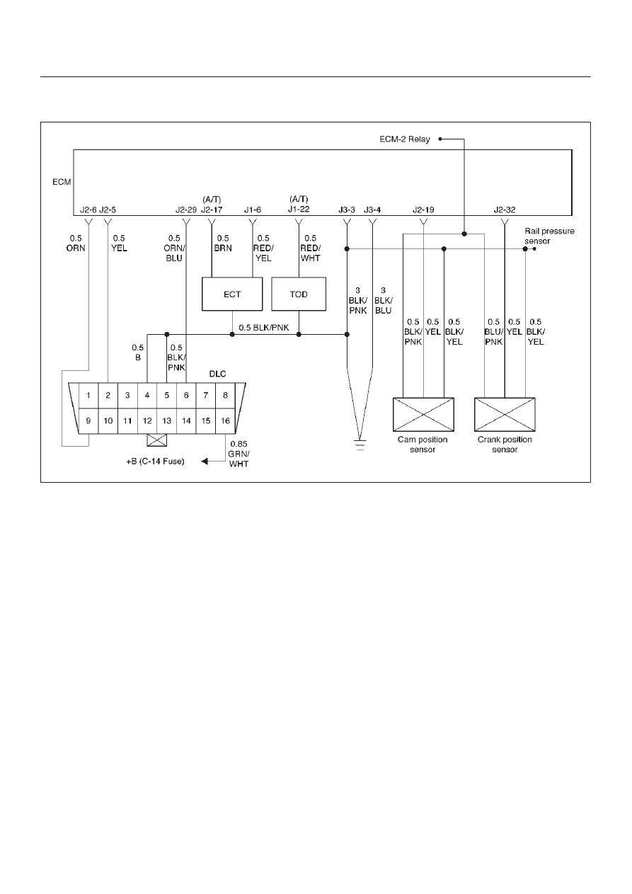
CKP (Crank Position) Sensor Out of Synchro

060RW133

Circuit Description

The CKP reference signal is produced by the crankshaft
position (CKP) sensor.  During one crankshaft revolution,
crankshaft pulses will be produced.  The Engine Control
Module ECM uses the CKP reference signal to calculate
engine RPM and crankshaft position.  If the ECM receives
an incorrect number of pulses on the CKP  reference
circuit, DTC P0336 will set.

Action Taken When the DTC Sets

D

The ECM will store conditions which were present
when the DTC was set as Freeze Frame and in the
Failure Records data.

Conditions for Clearing the MIL/DTC

D

DTC P0336 can be cleared by using the Tech 2 “Clear
Info” function or by disconnecting the ECM battery
feed.

Diagnostic Aids

An intermittent may be caused by a poor connection,
rubbed–through wire insulation or a wire broken inside the
insulation.  Check for:

D

Poor connection – Inspect the ECM harness and
connectors for improper mating, broken locks,
improperly formed or damaged terminals, and poor
terminal-to-wire connection.

D

Damaged harness – Inspect the wiring harness for
damage.  If the harness appears to be OK, disconnect
the ECM, turn the ignition on and observe a voltmeter
connected to the CKP reference circuit at the ECM
harness connector while moving connectors and
wiring harnesses related to the ECM.  A change in
voltage will indicate the location of the fault.

Reviewing the Failure Records vehicle mileage since the
diagnostic test last failed may help determine how often
the condition that caused the DTC to be set occurs.  This
may assist in diagnosing the condition.

6E–115

4JX1–TC ENGINE DRIVEABILITY AND EMISSIONS

DTC P0336 – CKP Sensor Out of Synchro


Step

Action

Value(s)

Yes

No

1

Was the “On-Board Diagnostic (OBD) System Check”
performed?

Go to 

Step 2

Go to 

OBD

System

Check

2

Attempt to start the engine.

Does the engine start?

Go to 

Step 3

Go to 

“Engine

Cranks But

Will Not Run”

chart

3

1. Review and record Failure Records information.
2. Clear DTC P0336.
3. Start the engine and idle for 1 minute.
4. Observe DTCs.

Is DTC P0336 set?

Go to 

Step 4

Refer to

Diagnostic

Aids

4

1. Disconnect the ECM and CKP sensor.
2. Check for an open or a short to ground in the CKP

reference circuit between the CKP sensor
connector and the ECM harness connector.

3. If a problem is found, repair as necessary.

Was a problem found?

Verify repair

Go to 

Step 5

5

1. Reconnect the ECM and CKP sensor.
2. Connect a DVM to measure voltage on the CKP

reference circuit at the ECM connector.

3. Observe the voltage while cranking the engine.

Is the voltage near the specified value?

2.5 V

Go to 

Step 8

Go to 

Step 6

6

Check the connections at the CKP sensor and replace
the terminals if necessary.

Did any terminals require replacement?

Verify repair

Go to 

Step 7

7

Replace the CKP sensor.

Is the action complete?

Verify repair

Go to 

Step 8

8

Check connections at the ECM and replace the
terminals if necessary.

Did any terminals require replacement?

Verify repair

Go to 

Step 9

9

Replace the ECM (Refer to the Data Programming in
Case of ECM change).

Is the action complete?

Verify repair

6E–116

4JX1–TC ENGINE DRIVEABILITY AND EMISSIONS

Diagnostic Trouble Code (DTC) P0337 (Flash DTC 43) 

CKP (Crank Position) Sensor No Signal

060RW133

Circuit Description

The CKP reference signal is produced by the crankshaft
position (CKP) sensor.  During one crankshaft revolution,
CKP  crankshaft reference pulses will be produced.  The
Engine Control Module ECM uses the CKP reference
signal to calculate engine RPM and crankshaft position.  If
the ECM does not receive pulses on the CKP reference
circuit, DTC P0337 will set.

Action Taken When the DTC Sets

D

The ECM will store conditions which were present
when the DTC was set as Freeze Frame and in the
Failure Records data.

Conditions for Clearing the MIL/DTC

D

DTC P0337 can be cleared by using the Tech 2 “Clear
Info” function or by disconnecting the ECM battery
feed.

Diagnostic Aids

An intermittent may be caused by a poor connection,
rubbed-through wire insulation or a wire broken inside the
insulation.  Check for:

D

Poor connection – Inspect the ECM harness and
connectors for improper mating, broken locks,
improperly formed or damaged terminals, and poor
terminal-to-wire connection.

D

Damaged harness – Inspect the wiring harness for
damage.  If the harness appears to be OK, disconnect
the ECM, turn the ignition on and observe a voltmeter
connected to the CKP reference circuit at the ECM
harness connector while moving connectors and
wiring harnesses related to the ICM.  A change in
voltage will indicate the location of the fault.

Reviewing the Failure Records vehicle mileage since the
diagnostic test last failed may help determine how often
the condition that caused the DTC to be set occurs.  This
may assist in diagnosing the condition.

6E–117

4JX1–TC ENGINE DRIVEABILITY AND EMISSIONS

DTC P0337 – CKP Sensor No Signal


Step

Action

Value(s)

Yes

No

1

Was the “On-Board Diagnostic (OBD) System Check”
performed?

Go to 

Step 2

Go to 

OBD

System

Check

2

Attempt to start the engine.

Does the engine start?

Go to 

Step 3

Go to 

Chart 3

3

1. Review and record Failure Records information.
2. Clear DTC P0337.
3. Start the engine and idle for 1 minute.
4. Observe DTCs.

Is DTC P0337 set?

Go to 

Step 4

Refer to

Diagnostic

Aid

4

1. Disconnect the CKP sensor.
2. Ignition “ON.”
3. Using a DVM, verify that 5 V reference and ground

are being supplied at the sensor connector (ECM
side).

Are 4-6 volts and ground available at the sensor?

Go to 

Step 7

Go to 

Step 5

5

1. Ignition “ON.”
2. With a DVM, backprobe the ECM connector 5 V

reference and ground connections.

Are 5 V reference and ground available at the ECM?

Go to 

Step 6

Go to 

Step 11

6

Check 5 V reference or ground between the CKP
sensor and ECM and repair the open circuit, short to
ground or short to voltage.

Is the action complete?

Verify repair

7

1. Ignition “OFF.”
2. Disconnect the ECM and CKP sensor.
3. Check for an open or a short to ground in the CKP

reference circuit between the CKP sensor
connector and the ECM harness connector.

4. If a problem is found, repair as necessary.

Was a problem found?

Verify repair

Go to 

Step 8

8

1. Reconnect the ECM and CKP sensor.
2. Connect a DVM to measure voltage on the CKP

reference circuit at the ECM connector.

3. Observe the voltage while cranking the engine.

Is the voltage near the specified value?

2.5 V

Go to 

Step 11

Go to 

Step 9

9

Check the connections at the CKP sensor and replace
the terminals if necessary.

Did any terminals require replacement?

Verify repair

Go to 

Step 10

10

Replace the CKP sensor.  Use caution and avoid hot oil
that may drip out.

Is the action complete?

Verify repair


Content   ..  1378  1379  1380  1381   ..