Opel Frontera UBS. Manual - part 1366


  Index      Opel     Opel Frontera UBS - service repair manual 1998-2002 year


Search            


Content   ..  1364  1365  1366  1367   ..


Opel Frontera UBS. Manual - part 1366


6E–58

4JX1–TC ENGINE DRIVEABILITY AND EMISSIONS

Diagnostic Trouble Code (DTC) P0108 (Flash DTC 34)

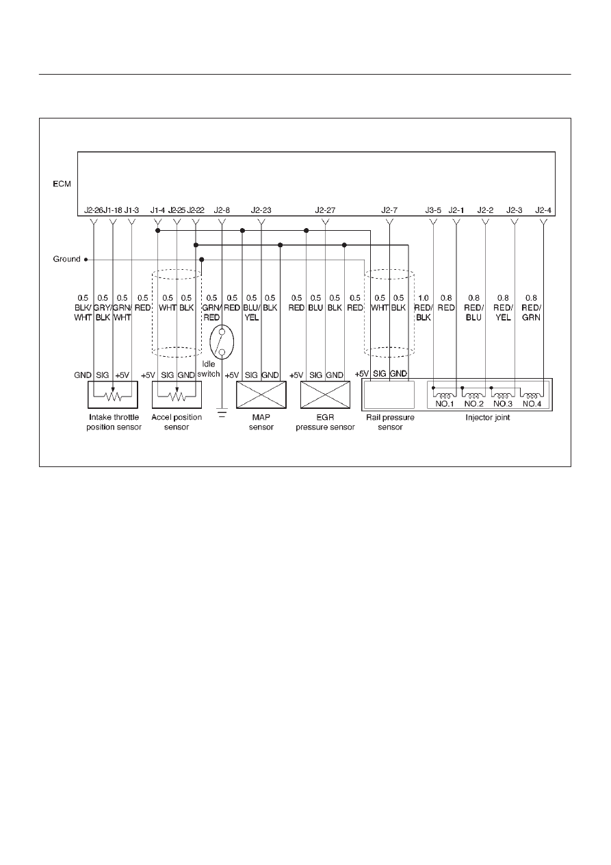
 MAP Sensor Circuit High Voltage

060RW134

Circuit Description

The manifold absolute pressure (MAP) sensor responds
to changes in intake manifold pressure (vacuum).
The ECM monitors the MAP signals for voltages outside
the normal range of the MAP sensor.  If the ECM detects a
MAP signal voltage that is excessively high, DTC P0108
will be set.

Action Taken When the DTC Sets

D

The ECM will illuminate the malfunction indicator lamp
(MIL) the first time the fault is detected.

D

The ECM will store conditions which were present
when the DTC was set as Freeze Frame and in the
Failure Records data.

Conditions for Clearing the MIL/DTC

D

DTC P0108 can be cleared by using the Tech 2 “Clear
Info” function or by disconnecting the ECM battery
feed.

Diagnostic Aids

Check for the following conditions:

D

Turn on the ignition switch and stop the engine. At this
time, the boost pressure will be equal to the
atmospheric pressure and the signal voltage will
increase.

D

Poor connection at ECM – Inspect harness connectors
for backed-out terminals, improper mating, broken
locks, improperly formed or damaged terminals, and
poor terminal-to-wire connection.

D

Damaged harness – Inspect the wiring harness for
damage.  If the harness appears to be OK, observe the
MAP display on the Tech 2 while moving connectors
and wiring harnesses related to the sensor.  A change
in the display will indicate the location of the fault.

If DTC P0108 cannot be duplicated, the information
included in the Failure Records data can be useful in
determining vehicle mileage since the DTC was last set. If
it is determined that the DTC occurs intermittently.

6E–59

4JX1–TC ENGINE DRIVEABILITY AND EMISSIONS

Sensor Circuit High Voltage


Step

Action

Value(s)

Yes

No

1

Was the “On-Board Diagnostic (OBD) System Check”
performed?

Go to 

Step 2

Go to 

OBD

System

Check

2

Put the engine into an idling status.

Is the MAP voltage value displayed on the Tech 2
above the specified value?

4 V

Go to 

Step 3

Go to 

Step 4

3

1. Turn off the ignition switch.
2. Remove the sensor connector connection.
3. Turn on the ignition switch “ON”.

Is the MAP voltage value displayed on the Tech 2 below
the specified value?

1 V

Go to 

Step 5

Go to 

Step 6

4

Is the MAP voltage value displayed on the Tech 2 below
the specified value?

1 V

Refer to

Chart P0107

Refer to

Diagnostic

Aids and

Symptom

Diagnosis

5

Connect the relay and solenoid checker
(5-8840-0386-0) to the battery voltage, then check the
sensor grounding circuit.

Does the checker lamp come on?

Go to 

Step 7

Go to 

Step 8

6

A voltage short circuit occurs in the MAP signal circuit
or this circuit is shorted with the 5V power circuit.
Repair the harness or Replace the ECM (Refer to the
Data Programming in Case of ECM change).

Is the action complete?

Verify repair

7

Replace the MAP sensor hose or the MAP sensor.

Is the action complete?

Verify repair

8

Repair the harness for open ground circuit.

Is the action complete?

Verify repair

6E–60

4JX1–TC ENGINE DRIVEABILITY AND EMISSIONS

Diagnostic Trouble Code (DTC) P0112 (Flash DTC 23)

 IAT Sensor Circuit Low Voltage

060RW129

Circuit Description

The Intake air temperature (IAT) sensor is a thermistor
which measures the temperature of the air entering the
engine.  The Engine Control Module ECM applies 5 volts
through a pull-up resistor to the IAT sensor.  When the
intake air is cold, the sensor resistance is high and the
ECM will monitor a high signal voltage on the IAT signal
circuit.  If the intake air is warm, the sensor resistance is
lower, causing the ECM to monitor a lower voltage.  DTC
P0112 will set when the ECM detects an excessively low
signal voltage on the Intake air temperature sensor signal
circuit.

Action Taken When the DTC Sets

D

The ECM will illuminate the malfunction indicator lamp
(MIL) the first time the fault is detected.

D

The ECM will store conditions which were present
when the DTC was set as Freeze Frame and in the
Failure Records data.

Conditions for Clearing the MIL/DTC

D

DTC P0112 can be cleared by using the Tech 2 “Clear
Info” function or by disconnecting the ECM battery
feed.

Diagnostic Aids

Check for the following conditions:

D

Poor connection at ECM – Inspect harness connectors
for backed-out terminals, improper mating, broken
locks, improperly formed or damaged terminals, and
poor terminal-to-wire connection.

D

Damaged harness – Inspect the wiring harness for
damage.  If the harness appears to be OK, observe the
IAT display on the Tech 2 while moving connectors and
wiring harnesses related to the IAT sensor. A change
in the IAT display will indicate the location of the fault.

If DTC P0112 cannot be duplicated, the information
included in the Failure Records data can be useful in
determining vehicle mileage since the DTC was last set.

6E–61

4JX1–TC ENGINE DRIVEABILITY AND EMISSIONS

Test Description

Number(s) below refer to the step number(s) on the
Diagnostic Chart:
2. Verifies that the fault is present.

3. If DTC P0112 can be repeated only by duplicating

the Failure Records condition, refer to the
Temperature vs. Resistance Value table.  The table
may be used to test the IAT sensor at various
temperatures to evaluate the possibility of a
“shifted” sensor that may be stored above or below
a certain temperature.  If this is the case, replace
the IAT sensor.  If the IAT sensor appears to be OK,
the fault is intermittent; refer to 

Diagnostic Aids.

Intake Air Temperature Sensor

°

C

°

F

Ohms

Temperature vs. Resistance Values

(approximate)

25

77

2796

15

59

4450

5

41

7280

DTC P0112 – IAT Sensor Low Voltage


Step

Action

Value(s)

Yes

No

1

Was the “On-Board Diagnostic (OBD) System Check”
performed?

Go to 

Step 2

Go to 

OBD

System

Check

2

1. Ignition “ON,” engine “OFF.”
2. Using a Tech 2, monitor the intake air temperature

(IAT).

Is the intake air temperature greater than the specified
value?

148

°

C

(283

°

F)

Go to 

Step 4

Go to 

Step 3

3

1. Ignition “ON,” engine “OFF.”  Review and record

Tech 2 Failure Records data.

2. Operate the vehicle within Failure Records

conditions as noted.

3. Using a Tech 2, monitor the “ DTC” info for DTC

P0112.

Does the Tech 2 indicate DTC P0112 failed this
ignition?

Refer to 

Test

Description

Refer to

Diagnostic

Aids

4

1. Ignition “OFF.”
2. Disconnect the IAT sensor electrical connector.
3. Ignition “ON.”
4. Observe the manifold air temperature on the Tech 2.

Is the manifold air temperature below the specified
value?

–38

°

C

(–36

°

F)

Go to 

Step 6

Go to 

Step 5

5

1. Ignition “OFF.”
2. Disconnect the ECM electrical connectors.
3. Check the IAT sensor signal circuit for a short to

ground.

Is the IAT sensor signal circuit shorted to ground?

Verify repair

Go to 

Step 7

6

Replace the IAT sensor.

Is the action complete?

Verify repair

7

Replace the ECM (Refer to the Data Programming in
Case of ECM change).

Is the action complete?

Verify repair


Content   ..  1364  1365  1366  1367   ..