Opel Frontera UBS. Manual - part 1287


  Index      Opel     Opel Frontera UBS - service repair manual 1998-2002 year


Search            


Content   ..  1285  1286  1287  1288   ..


Opel Frontera UBS. Manual - part 1287


4JG2-NA/4JG2-TURBO ENGINE 6A 2– 29

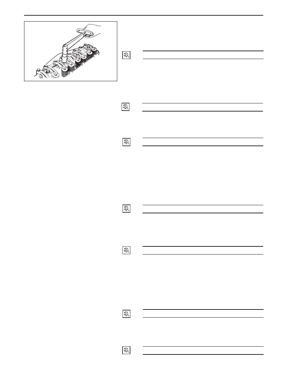
23. Rocker Arm Shaft Assembly

Loosen all adjusting screws.

Align fixing bolts to not of rocker arm shaft and
tighten them to the specified torque.

Valve clearance adjustment.

Refer to valve clearance adjustment steps in
section 00.

22. Fuel Leak Off Pipe

Install fuel leak off pipe with new copper gasket
and tighten joint bolts to the specified torque.

54 (5.5/40)

N·m (kg·m/lb·ft)

21. Injection Pipe

Install injection pipes and sleeve nuts securely and
tighten them to the specified torque.

29 (3.0/22)

N·m (kg·m/lb·ft)

29 (3.0/22)

N·m (kg·m/lb·ft)

20. Glow Plug Harness
19. Cylinder Head Cover

Apply engine oil to the rocker arms and the valve
spring.

Install the cylinder head cover gasket to the
cylinder head cover.

Tighten the cylinder head cover nuts to the
specified torque in the numerical order shown in
the illustration.

18. Fuel Leak Off Hose
17. Front Exh. Pipe

Install front exhaust pipe and tighten fixing bolts to
the specified torque.

13 (1.3/113)

N·m (kg·m/lb·in)

19 (1.9/14)

N·m (kg·m/lb·ft)

16. Exh. Manifold W/turbo  (4JG2-T Only)

Install manifold gasket in cylinder head.

Insert exh. manifold into studs on cylinder head a
little.

Under this condition, insert oil return pipe frange
into studs on crankcase.

Tighten exh. manifold fixing bolts and nut to
specified torque.

26 (2.7/20)

N·m (kg·m/lb·ft)

15. Oil Cooler Hose
14. Oil Return Pipe: Turbo (4JG2-T Only)

Tighten joint bolt to the specified torque.

8 (0.8/69)

N·m (kg·m/lb·in)

6A2 – 30 4JG2-NA/4JG2-TURBO ENGINE

13. Oil Feed Pipe: Turbo (4JG2-T Only)

Tighten joint bolts (cylinder block and turbo
charger side) to the specified torque.

12. Water Outlet Hose: Turbo (4JG2-T Only)

Connect to water inlet pipe of engine.

11. Water Inlet Hose: Turbo (4JG2-T Only)

Connect to water outlet pipe.

10. Water Bypass Hose

Water bypass hose connect to water inlet pipe.

9.

Heater Hose

Connect to heater pipe.

8.

Engine Harness

Connect five harness connecters to units on
thermostat housing.

7.

Water Hose: CSD

6.

A/C Compressor

Tighten temporarily fixing bolts (upper and front
lower sides of compressor.)

Tighten fixing bolt (rear under side of compressor)
to the specified torque by using a long extension
bar and torque wrench at under side of wheel arch.

Tighten fixing bolts (front upper and lower sides of
compressor) to the specified torque.

5.

P/S Pump Drive Belt

Install drive belts adjust belt tension by adjusting
bolt and tighten locking bolt to the specified
torque.

Refer to “Drive Belt Adjustment” in section 6B.

4.

Oil Level Gauge Guide Tube

Tighten guide tube to the specified torque.

23 (23/17)

N·m (kg·m/lb·ft)

37 (3.8/27)

N·m (kg·m/lb·ft)

40 (4.1/30)

N·m (kg·m/lb·ft)

19 (1.9/14)

N·m (kg·m/lb·ft)

3.

Intercooler Assembly (4JG2-T Only)

Refer to “Drive Belt Adjustment” in section 6B.

2.

Intake Air Duct (4JG2-T Only)

1.

Radiator Hose Upper

Connect to water outlet pipe.

4JG2-NA/4JG2-TURBO ENGINE 6A2 – 31

CRANKCASE

REMOVAL

Preparation

Disconnect battery ground cable.

Lift up car.

Drain engine oil.

NOTE

Install drain plug with new gasket.

1. Transmission Housing Bolt

Remove six fixing bolts from under side of hous-

ing.

2. Oil Return Pipe: Turbo (4JG2 -T only)

Remove return pipe fixing nuts and set return pipe
frange from stud on crankcase.

3. Oil Pipe Clip Bolt: Vaccum Pump

4. Oil Level Gauge Guide Tube

Remove two guide tube stay fixing bolts.

Disconnect blow by hose and remove oil level
gauge guide tube.

6A2 – 32 4JG2-NA/4JG2-TURBO ENGINE

5. Vacuum Hose

6. Crankcase

Remove crankcase fixing bolts two fixing bolts for
rear oil seal arch parts on crankcase could be
removed extention universal joint box wrench.

Remove crankcase by using crankcase seal cutter
to shear sealant off and remove crankcase.
Oil seal cutter: 5-8840-2153-0

NOTE

Don’t ply crankcase or you may distort sealing
surface.

Distorted or damaged crankcase should not by
used.

INSTALLATION

6.

Crankcase

Completely remove all sesidual sealant, lubricant
and moisture from the sealing surface of
crankcase and cylinder block.

Apply a correct width bead of sealant (TB-1207C or
its equivalent) to contact surface of crankcase
there must be no gaps in the bead.

Install crankcase with cylinder-block, and tighten
fixing bolts to the specified torque.

5. Vacuum Hose

4. Oil Level Gauge Guide Tube

Install guide tube to the specified torque.

Connect blow by hose to guide tube.

3. Oil Pipe Clip Bolts: Vacuum Pump

Tighten oil pipe clip fixing bolts to the specified
torque.

2. Oil Return Pipe: Turbo.

Tighten fixing nuts to crankcase to the specified
torque.

1. Transmission Housing Bolts

Pour engine oil into engine.

Install battery ground cable.

Start the engine and check for oil leakage from
crankcase.

19 (1.9/14)

N·m (kg·m/lb·ft)

19 (1.9/14)

N·m (kg·m/lb·ft)

19 (1.9/14)

N·m (kg·m/lb·ft)

8 (0.8/69)

N·m (kg·m/lb·in)


Content   ..  1285  1286  1287  1288   ..