Opel Frontera UBS. Manual - part 1286


  Index      Opel     Opel Frontera UBS - service repair manual 1998-2002 year


Search            


Content   ..  1284  1285  1286  1287   ..


Opel Frontera UBS. Manual - part 1286


4JG2-NA/4JG2-TURBO ENGINE 6A2 – 25

INSTALLATION

5.

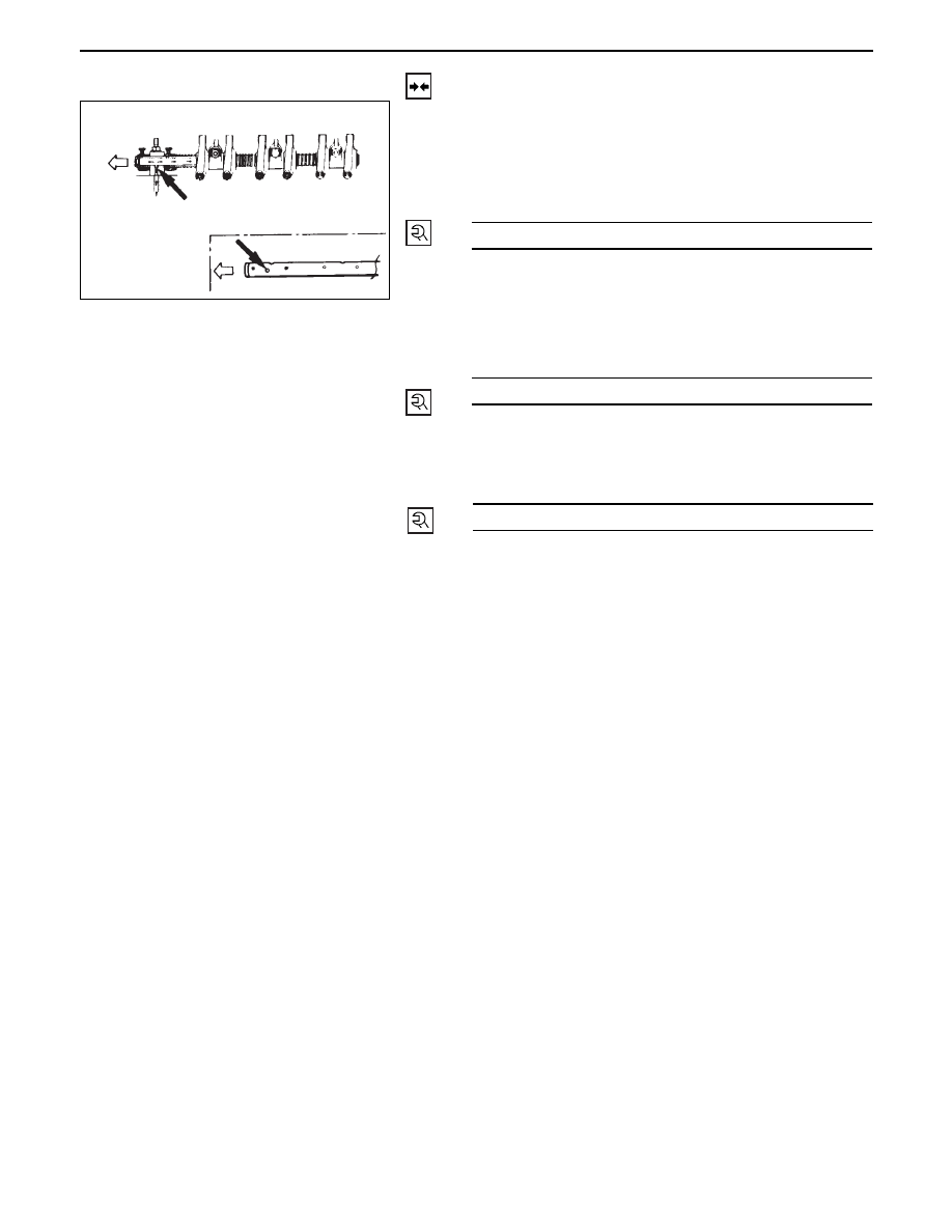
Rocker Arm Shaft Assembly

•

Install  rocker arm shaft with larger oil hole (ø4) to
the front of engine.

•

Align fixing bolt with not of rocker arm shaft and
tighten fixing bolts to the specified torque.

54 (5.5/40)

N·m (kg·m/lb·ft)

•

Adjust valve clearance refreshing to section valve
clearance adjustment.

4.

Cylinder Head Cover

•

Install cylinder head cover and tighten bolts to the
specified torque.

3.

Oil Level Gauge Guide Tube

•

Tighten guide tube to the specified torque.

2.

Intercooler Assembly (4JG2-T Only)

•

Refer to intercooler installation steps in this
section.

1.

Air Cleaner Cover & Air Duct (4JG2-T Only)

13 (1.3/113)

N·m (kg·m/lb·in)

19 (1.9/14)

N·m (kg·m/lb·ft)

6A2 – 26 4JG2-NA/4JG2-TURBO ENGINE

CYLINDER HEAD

4JG2-NA/4JG2-TURBO ENGINE 6A 2– 27

REMOVAL

Preparation

•

Remove battery.  (two batteries for cold area)

•

Disconnect window washer hose, and remove
engine hood.

•

Drain coolant.

•

Space stand and front right tire.

1.

Radiator Hose : Upper

•

Disconnect upper radiator hose from engine side.

2.

Air Cleaner Cover & Air Duct

3.

Intercooler Assembly (4JG2-T Only)

•

(Refer to intercooler removal steps in this section)

4.

Oil Level Gauge Guide Tube

5.

P/S Pump

•

Loosen P/S pump fixing bolts and adjusting bolt
and remove two drive belts.

•

Remove two fixing bolts (front side).  A fixing nut
(rear side) and support P/S pump asm with oil
hoses by tying to body side.

6.

A/C Compressor Assembly

•

Remove A/C compressor fixing bolt (rear under
side of compressor) by using a long extension bar
at under side of wheel arch.

•

Disconnect magnetic clutch harness connector.

•

Remove fixing bolts (upper and front lower side of
compressor) and set A/C compressor asm with
pipe line on battery carrier.

7.

Water Hose; CSD

•

Disconnect CSD water hoses from heater hose
side.

8.

Engine Harness

•

Disconnect five harness connectors from units on
thermostat housing.

9.

Heater Hose: Rear Side

•

Disconnect heater hose from heater pipe.

10. Water Bypass Hose

•

Disconnect water bypass hose from water pump.

11. Water Inlet Hose: Turbo (4JG2-T Only)

•

Disconnect from water outlet pipe of engine.

12 Water Outlet Hose: Turbo (4JG2-T Only)

•

Disconnect from water inlet pipe of engine.

13 Oil Feed Pipe: Turbo (4JG2-T Only)

•

Remove two joint bolts (from turbocharger and
cylinder block) and oil feed pipe.

14. Oil Return Pipe Fixing Nut (4JG2-T Only)

•

Remove oil return pipe fixing nut from cylinder
block.

15. Oil Cooler Hose

6A2 – 28 4JG2-NA/4JG2-TURBO ENGINE

16. Exh. Manifold; W/turbo (4JG2-T Only)

•

Remove exh. manifold bracket fixing bolt from
exh. manifold.

•

Remove exh. manifold fixing bolts and nuts from
cylinder head.

•

After pulling out exh. manifold a little, remove oil
return pipe flange from stud bolt and remove exh.
manifold w/turbo.

17. Front Exhaust Pipe
18. Fuel Leak Off Hose
19. Cylinder Head Cover
20. Glow Plug Harness
21. Injection Pipe

•

Loosen sleeve nuts on injection pump side.

•

Disconnect sleeve nuts on injection pipe.

22. Fuel Leak Off Pipe
23. Rocker Arm Shaft Assembly
24. Push Rod
25. Cylinder Head W/inlet Manifold

•

Disconnect cylinder head bolts in sequence shown
in Figure.

26. Cylinder Head Gasket

INSTALLATION

26. Cylinder Head Gasket

•

Determine cylinder head gasket grade by
measuring projection of piston head.

•

Install dowel in cylinder block.

•

Install cylinder head gasket with top mark up.

25. Cylinder Head W/intake Manifold

•

Clean up cylinder head lower surface and cylinder
body upper surface.

•

Install cylinder head as softly.

•

Apply engine oil to screw and seat of cylinder
head bolts.

•

Tighten cylinder head bolts in following sequence.

24. Push Rod

•

Inspect curvature, excessive wear and damage.
(Refer to push rod inspection)

1st Step

N·m (kg·m/lb·ft)

49 (5.0/36)

2nd Step

60°

3rd Step

60°


Content   ..  1284  1285  1286  1287   ..