Opel Frontera UBS. Manual - part 1276


  Index      Opel     Opel Frontera UBS - service repair manual 1998-2002 year


Search            


Content   ..  1274  1275  1276  1277   ..


Opel Frontera UBS. Manual - part 1276


ENGINE MECHANICAL 6A – 37

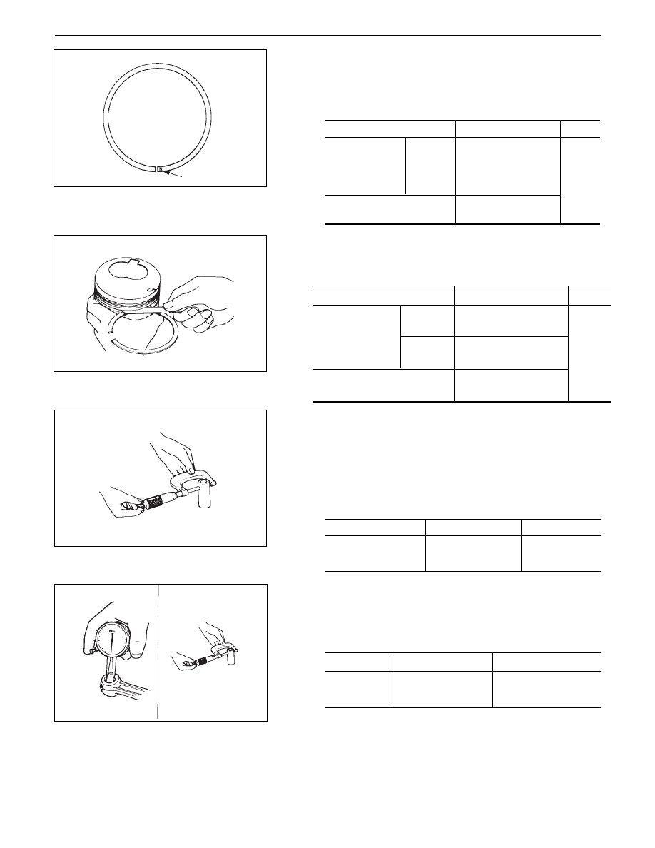
Push the ring by the piston, at a right angle to the
wall, into the point at which the cylinder bore
diameter is the smallest.

Measure the ring end gap.

Standard

Compression
ring

Limit

1st/2nd

0.20-0.35

(0.0079-0.0138)

1.5

(0.0591)

0.10-0.30

(0.0039-0.0118)

Oil ring

mm(in)

2.

Measure the clearance between the piston ring groove
and the piston ring with a feeler gauge.  If the piston ring
groove/piston ring clearance exceeds the specified limit,
the piston must be replaced.

Standard

Compression
ring

Limit

Top

0.05-0.09

(0.0020-0.0035)

2nd

0.05-0.09

(0.0020-0.0035)

0.15

(0.0059)

0.03-0.07

(0.0012-0.0028)

Oil ring

mm(in)

Piston pin

Visually inspect the piston pin for cracks, flaws, and other
damage and replace if necessary.

1.

Use a micrometer to measure the piston pin outside
diameter in both directions at three different
positions.  If the measurement exceed the specified
limit, the piston pin must be replaced.

Standard

Piston pin outside
diameter

Limit

33.995-34.000

(1.3384-1.3386)

33.970

(1.3374)

mm (in)

2.

Measure the inside diameter of the connecting rod
small end.  If the clearance between the small end
and pin does not conform to the specified value, the
connecting rod or bushing and pin must be replaced.

Standard

Limit

0.008 ~ 0.020

(0.0003 ~ 0.0008)

0.05

(0.0020)

Clearance

mm (in)

6A – 38 ENGINE MECHANICAL

NOTE:

Align the bushing with the connecting rod oil port.
After installing a new bushing, finish the bushing bore
with a pin hole grinder.

3.

Insert the piston pin into the piston and rotate it.  If
the pin rotates smoothly with no backlash, the
clearance is normal.  If there is backlash or
roughness, measure the clearance.  If the clearance
exceeds the specified limit, the piston and the piston
pin must be replaced.

Standard

Limit

0.002 ~ 0.015

(0.00008 ~ 0.0006)

0.04

(0.0016)

Clearance

mm (in)

Bushing replacement

Removal:

Use a suitable bar and bench press or
hammer.

Installation:

Use a suitable bar and bench press.

Connecting rods

1.

Check the connecting rod alignment with a
connecting rod aligner.
If either the bend or the twist exceeds the specified
limit, the connecting rod must be replaced.

2.

Measure the connecting rod thrust clearance.
Use a feeler gauge to measure the thrust clearance at
the big end of the connecting rod.
If the clearance exceeds the specified limit, the
connecting rod must be replaced.

Standard

Limit

0.230 (0.0091)

0.350 (0.0138)

mm (in)

Limit

Bend per 100 (3.937)

Twist per 100 (3.937)

mm (in)

0.20 (0.0079)

0.15 (0.0059)

Standard

0.08 (0.0031) or less

0.05 (0.0020) or less

ENGINE MECHANICAL 6A – 39

3.

Measure the oil clearance between the connecting
rod and the crankshaft by:
1) Remove the connecting rod cap nuts and the rod

caps.
Arrange the removed rod caps in the cylinder
number order.

2) Clean the rod bearings and the crankshaft pins.
3) Carefully check the rod bearings.

If even one bearing is found to be damaged or
badly worn, the entire bearing assembly must be
replaced as a set.  Reinstall the bearings in their
original positions.
Apply plastigage to the crank pin.

4) Reinstall the rod caps to their original positions.
5) Tighten the cap nuts in 2 steps, using angular

tightening method as shown in the following
specifications.

NOTE:

Do not allow the crankshaft to rotate.

N·m (kg·m/lb·ft)

45

°

 ~ 60

°

1st step

2nd step

29 (3.0/22)

6) Remove the rod caps.
7) Measure the width of the plastigage and determine

the oil clearance.  If the oil clearance exceeds the
limit, replace the rod bearings as a set.

8) Clean the plastigage from the bearings and the

crankshaft pins.

REASSEMBLY

10. Connecting Rod

9.

Piston

8.

Piston Pin

Apply a coat of engine oil to the piston pin and the
piston pin hole.

7.

Piston Pin Snap Ring

Apply a thin coat of engine oil to the piston pin.
Try to insert the piston pin into the piston pin hole
with normal finger pressure.
Weigh each piston and connecting rod assembly.
Select piston and connecting rod combinations so
that the weight variation of the different assemblies
is held within the specified limits.

Variance in weight
after assembly

Less than 3

(0.1058)

g (oz)

Standard

Limit

0.029 (0.0011) – 0.083 (0.0033)

0.100 (0.0039)

mm (in)

NOTE:

When changing piston/connecting rod combinations, do
not change the piston/piston pin combination.

6A – 40 ENGINE MECHANICAL

6.

Piston Ring

Install the piston rings with the piston ring expander.
The compression ring must be set with the 1N, 2N
mark facing up.

Discrimination mark is painted as shown in the
illustration.

Attach the piston to the connecting rod with the
piston front mark and the connecting rod ISUZU
mark on the same side.

Install piston rings in the following sequence.

1) Oil ring

1 Expander ring

2) 2nd compression ring
3) 1st compression ring

The compression ring must be set with the 1N or
2N mark facing up.

1st compression ring: N

2nd compression ring: 2N

After installation, apply engine oil to the entire
circumference of the piston rings.
Check to see that all the rings rotate smoothly.

Insert the bearings into the connecting rods and
caps.
Apply new engine oil to the bearing faces.
Cap side bearings have no oil hole.
Conn rod side bearing’s oil hole should be aligned
with oil hole on the conn rod.


Content   ..  1274  1275  1276  1277   ..