Index Opel Opel Frontera UBS - service repair manual 1998-2002 year
Search
Content .. 125 126 127 128 ..
Opel Frontera UBS. Manual - part 127
4A2B–28
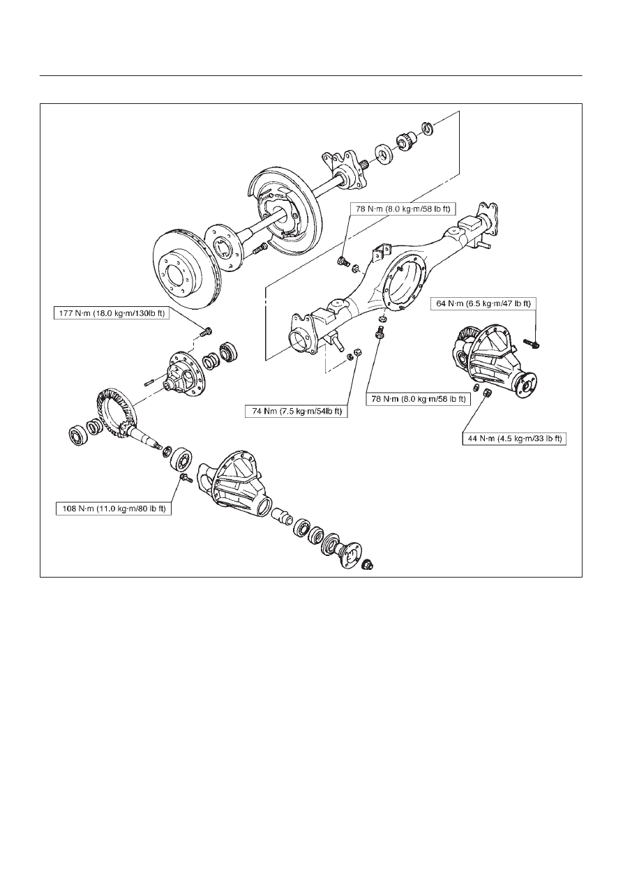
DIFFERENTIAL (REAR 244mm)
Torque Specifications
E04RW019