Opel Frontera UBS. Manual - part 1239


  Index      Opel     Opel Frontera UBS - service repair manual 1998-2002 year


Search            


Content   ..  1237  1238  1239  1240   ..


Opel Frontera UBS. Manual - part 1239


6E–322

ENGINE DRIVEABILITY AND EMISSIONS

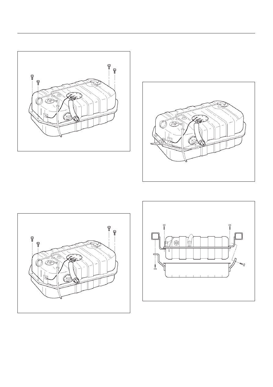
15. Remove the fuel tank retaining bolts on both sides.
16. Remove the fuel tank.

TS23770

Installation Procedure

1. Install the fuel tank.

D

Place the flanges on the left and right side of the
tank on the bracket.

2. Install the fuel tank retaining bolts.

Tighten

D

Tighten the fuel tank retaining bolts to 36 N·m (27 lb
ft.).

TS23770

3. Connect the fuel return hose.
4. Connect the fuel supply hose.
5. Connect the EVAP vapor hose.
6. Connect the wiring connector for the fuel gauge unit.
7. Connect the fuel gauge wiring connector to the

bracket.

8. Connect the wiring connector for the fuel pump.

TS23769

9. Install the undercover.
10. Secure the undercover with the retaining bolts.

TS23797

6E–323

ENGINE DRIVEABILITY AND EMISSIONS

11. Connect the fuel filler fuse at the tank.
12. Connect the air breather hose at the tank.

TS23796

13. Fill the fuel tank with fuel.
14. Tighten the fuel filler cap.
15. Connect the negative battery cable.

Throttle Body (TB)

Removal Procedure

1. Disconnect the negative battery cable.
2. Drain the cooling system.  Refer to 

Cooling System.

3. Remove the accelerator cable assembly.  Refer to

Accelerator Cable in Engine Speed Control System..

4. Disconnect the electrical connectors:

D

Throttle position (TP) sensor.

D

Idle air control (IAC) solenoid.

D

Intake air temperature (IAT) sensor.  Refer to
Intake Air Temperature Sensor.

035RW023

5. Disconnect the vacuum hose below the air horn.
6. Remove the intake air duct clamp.
7. Disconnect the intake air duct.
8. Disconnect the coolant lines from the throttle body.
9. Remove the bolts from the common chamber.
10. Remove the throttle body from the common chamber.
11. Remove the gasket from the upper intake manifold.

035RW024

12. Remove the IAC.  Refer to 

Idle Air Control (IAC)

Solenoid.

13. Remove the TP sensor.  Refer to 

Throttle Position

(TP) Sensor.

Inspection Procedure

NOTE: Do not use solvent of any type when you clean the
gasket surfaces on the intake manifold and the throttle
body assembly.  The gasket surfaces and the throttle
body assembly may be damaged as a result.

D

If the throttle body gasket needs to be replaced,
remove any gasket material that may be stuck to the
mating surfaces of the manifold.

D

Do not leave any scratches in the aluminum casting.

Installation Procedure

1. Install the TP sensor.  Refer to 

Throttle Position (TP)

Sensor.

2. Install the IAC.  Refer to 

Idle Air Control (IAC)

Solenoid.

3. Install the gasket on the common chamber.
4. Install the throttle body on the common chamber.

6E–324

ENGINE DRIVEABILITY AND EMISSIONS

5. Secure the gasket and the throttle body with the four

bolts.

D

The vacuum lines must be properly routed under
the throttle body before tightening the mounting
bolts.

Tighten

D

Tighten the throttle body mounting bolts to 24 N·m
(17 lb ft.).

035RW024

6. Install the coolant lines.
7. Connect all the vacuum lines.
8. Install the intake air duct.
9. Tighten the intake air duct clamp.
10. Connect all the electrical connectors:

D

Throttle position (TP) sensor.

D

Idle air control (IAC) solenoid.

D

Intake air temperature (IAT) sensor.  Refer to
Intake Air Temperature Sensor.

035RW023

11. Install the accelerator cable assembly.  Refer to

Accelerator Cable in Engine Speed Control System..

12. Fill the cooling system.  Refer to 

Cooling System.

13. Install the negative battery cable.

Electronic Ignition System

Removal Procedure

1. Disconnect the negative battery cable.
2. Disconnect the electrical connector at the ignition coil.
3. Remove the two screws that secure the ignition coil to

the rocker cover.

014RW108

4. Remove the ignition coil and the spark plug boot from

the spark plug.

D

Twist the ignition coil while pulling it straight up.

014RW091

5. Use the spark plug socket in order to remove the

spark plug from the engine.

6E–325

ENGINE DRIVEABILITY AND EMISSIONS

Spark Plug Gap Check

D

Check the gap of all spark plugs before installation.

D

Use a round wire feeler gauge to ensure an accurate
check.

D

Plugs installed with the wrong gap can cause poor
engine performance and excessive emissions.

Installation Procedure

NOTE: The plug must thread smoothly into the cylinder
head and be fully seated.  Use a thread chaser if
necessary to clean the threads in the cylinder head.
Cross-threading or failure to fully seat the spark plug can
cause plug overheating, exhaust blow-by gas, or thread
damage.  Do not overtighten the spark plugs.  Over
tightening can cause aluminum threads to strip.

1. Install the spark plug in the engine.  Use the

appropriate spark plug socket.

Tighten

D

Tighten the spark plug to 18 N·m (13 lb ft.).

2. Install the ignition coil and spark plug boot over the

spark plug.

014RW108

3. Secure the ignition coil to the rocker cover with two

screws.

014RW091

4. Connect the electrical connector at the ignition coil.
5. Connect the negative battery cable.

Catalytic Converter

Removal and Installation Procedure

Refer to 

Engine Exhaust in Engine.

Air Conditioning Relay

Removal Procedure

1. Remove the fuse and relay box cover from under the

hood.

2. Consult the diagram on the cover to determine which

is the correct relay.

3. Insert a small screwdriver into the catch slot on the

forward side of the fuel pump relay.

D

The screwdriver blade will release the catch inside.

T321092


Content   ..  1237  1238  1239  1240   ..