Opel Frontera UBS. Manual - part 1114


  Index      Opel     Opel Frontera UBS - service repair manual 1998-2002 year


Search            


Content   ..  1112  1113  1114  1115   ..


Opel Frontera UBS. Manual - part 1114


POWER ASSISTED BRAKE SYSTEM  5C – 61
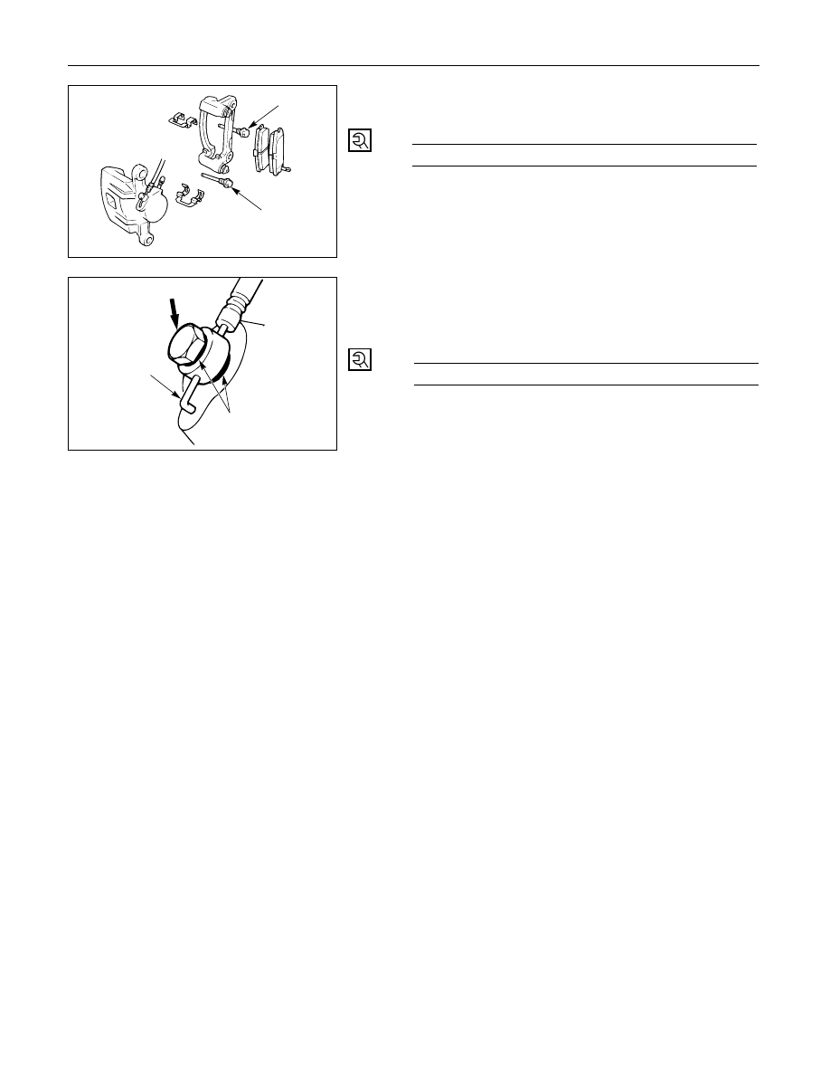
4. Guide Bolt

3. Lock Bolt

Lock Bolt Torque

N·m (kg·m / lb·ft)

44 (4.5 / 32)

3

4

2. Brake Flexible Hose

1) Always use new gaskets.
2) Be sure to put the hooked edge of the flexible

hose end into the anti-rotation cavity.

Brake Flexible Hose Torque

N·m (kg·m / lb·ft)

35 (3.5 / 26)

Hooked edge

Gasket

1. Wheel and Tire Assembly

1) Refer to Wheels and Tires in Suspension section.
2) Bleed brakes.

5C – 62 POWER ASSISTED BRAKE SYSTEM

REBUILDING THE CALIPER

3

4

6

5

7

9

1

2

3

8

Disassembly Steps

1.

Guide bolt

2.

Lock bolt

3.

Dust boot

4.

Dust boot ring

5.

Piston

6.

Dust boot; piston

7.

Piston seal

8.

Bleeder with cap

9.

Caliper body

Reassembly Steps

9.

Caliper body

8.

Bleeder with cap

7.

Piston seal

5.

Piston

6.

Dust boot; pisotn

4.

Dust boot ring

3.

Dust boot

2.

Lock bolt

1.

Guide bolt

DISASSEMBLY

1. Guide Bolt

2. Lock Bolt

3. Dust Boot

4. Dust Boot Ring

Using a small screwdriver, remove the dust boot
ring.

POWER ASSISTED BRAKE SYSTEM  5C – 63

5. Piston

Insert a block of wood into the caliper and force
out the piston by blowing compressed air into the
caliper at the flexible hose attachment. This
procedure must be done prior to removal of dust
boot.

WARNING:
DO NOT PLACE YOUR FINGERS IN FRONT OF THE
PISTON IN AN ATTEMPT TO CATCH OR PROTECT IT
WHEN APPLYING COMPRESSED AIR. THIS COULD
RESULT IN PERSONAL INJURY.

CAUTION:
Use just enough air to ease the piston out of the
bore. If the piston is blown out, it may be damaged.

6. Dust Boot; Piston

7. Piston Seal

8. Bleeder with Cap

9. Caliper Body

REASSEMBLY

9. Caliper Body

8. Bleeder with Cap

Bleeder Torque

N·m (kg·cm / lb·in)

8 (80 / 69)

7. Piston Seal

Apply special rubber grease to the piston seal and
cylinder wall, then insert the piston seal into the
cylinder. The special rubber grease is included in
the repair kit.

INSPECTION AND REPAIR

Make necessary parts replacement, if wear, damage,
corrosion or any other abnormal conditions are found
through inspection.
Check the following parts;

Rotor

Cylinder body

Cylinder bore

Piston

Slide pin

Support bracket

NOTE:
The piston dust seal and dust boot are to be replaced
each time the caliper is overhauled.
Discard these used rubber parts and replace with
new ones.

5. Piston

5C – 64 POWER ASSISTED BRAKE SYSTEM

6. Dust Boot; Piston

When inserting the piston into the cylinder, use
finger pressure only. Do not use a mallet or other
impact tools, since damage to the cylinder wall or
piston seal can result.

4. Dust Boot Ring

Apply special grease (Approx. 1 g) to the piston
and attach the dust boot to the piston and caliper.
Insert the dust boot ring into the dust boot.

3. Dust Boot

Install the dust boot on the support bracket after
applying special grease (Approx 1 g) onto the
dust boot inner surface. Also apply special grease
onto the lock bolt and guide bolt setting hole of
the support bracket.

2. Lock Bolt

1. Guide Bolt

Guide Bolt Torque

N·m (kg·m / lb·ft)

44 (4.5 / 32)


Content   ..  1112  1113  1114  1115   ..