Content .. 1111 1112 1113 1114 ..
Opel Frontera UBS. Manual - part 1113
POWER ASSISTED BRAKE SYSTEM 5C – 57
3. Caliper Assembly
•
Support the caliper assembly so that the brake
hose is not stretched or damaged.
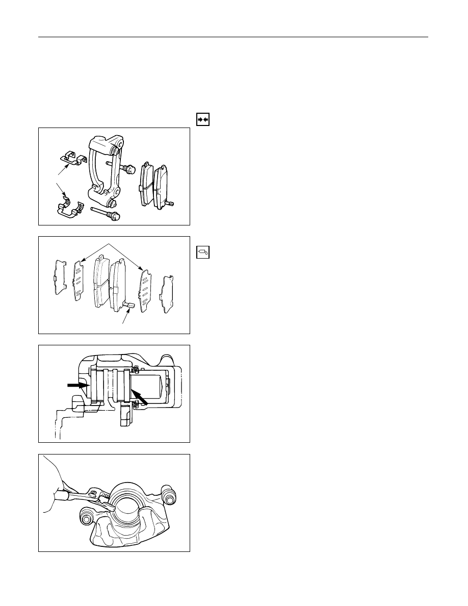
4. Pad Assembly with Shim
5. Clip
INSTALLATION
5. Clip
Clip
4. Pad Assembly with Shim
•
Apply special grease (approx. 0.2 g) to both
contacting surfaces of inner shims. Wipe off
extruded grease after installing.
Inner shim
Wear indicator
Apply
special
grease
3. Caliper Assembly
1) Use adjustable pliers to bottom the piston into the
caliper bore. Be careful not to damage the piston
dust boot.
2) Do not damage the flexible hose by twisting or
pulling it.