Opel Frontera UBS. Manual - part 1058


  Index      Opel     Opel Frontera UBS - service repair manual 1998-2002 year


Search            


Content   ..  1056  1057  1058  1059   ..


Opel Frontera UBS. Manual - part 1058


4C–49

DRIVE SHAFT SYSTEM

Removal

1. Jack up the vehicle and support it on the chassis

stands.

2. Gear shift lever should be placed in neutral position

and parking brake released.

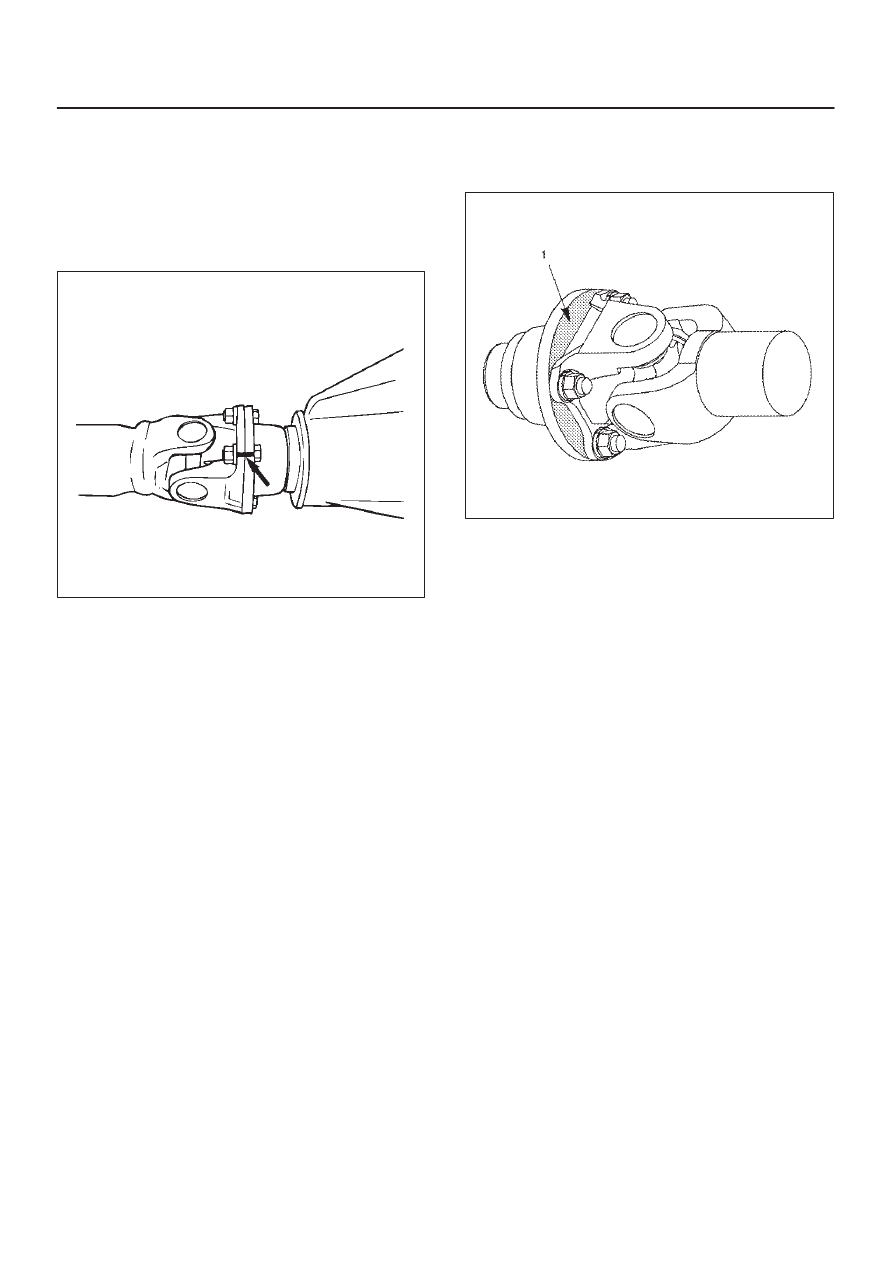
NOTE: Apply alignment marks on the flange at the rear
propeller shaft both front and rear side.

401RS023

3. Remove bolt, nut and washer (Rear axle side).
4. Remove bolt, nut and washer (Transfer side).
5. Remove rear propeller shaft.

Installation

NOTE: Never install the shaft assembly backwards.

1. Completely remove the black paint from the

connecting surface of flange coupling on each end of
propeller shaft. Clean so that no foreign matter will be
caught in between.

2. Align the mark which is applied at removal .

Install rear propeller shaft and tighten the bolts to the
specified torque.

Torque: 63 N·m  (6.4 kg·m/46 lb ft)

3. After installing the propeller shaft, be sure to apply

black paint (1) to exposed area (other than
connecting surface) of the entire surface of flange
coupling .

401RS022

4C–50

DRIVE SHAFT SYSTEM

Disassembly

401RW057

Legend

(1) Sleeve Yoke

(2) Seal
(3) Tube Assembly

1. Apply alignment marks (1) on the sleeve yoke and

tube assembly then remove sleeve yoke.

401RW056

2. Remove seal.
3. Remove tube assembly.

4C–51

DRIVE SHAFT SYSTEM

Universal Joint Disassembly

401RW054

Legend

(1) Flange Yoke
(2) Spider with Grease Fitting

(3) Snap Ring
(4) Needle Roller Bearing
(5) Grease Fitting

1. Apply alignment marks (1) on the yokes of the

universal joint, then remove snap ring.

401RS028

2. Tap out the needle roller bearing by gently striking the

shoulder of the yoke, using a mallet or a copper
hammer.

401RS006

4C–52

DRIVE SHAFT SYSTEM

3. Make sure of proper position for reinstallation by

applying setting marks, then remove spider with
grease fitting.

Inspection and Repair

Make necessary correction or parts replacement if wear,
damage, corrosion or any other abnormal condition is
found through inspection.

NOTE: When any part of the journal assembly (spider,
needle roller bearing, grease fitting) requires
replacement, be sure to replace the entire assembly.
Check the following parts for wear, damage, noise or any
other abnormal conditions:

1. Spider
2. Needle roller bearing
3. Yoke
4. Flange

Outside Diameter of Spider Pin

Standard: 17.00 mm (0.669 in)

Limit: 16.90 mm (0.665 in)

401RS007

Propeller Shaft Run-out

Support the ends of the propeller shaft on V-blocks (2)
and check for run-out by holding the probe of a dial
indicator (1)  in contact with the center part of the shaft.  If
the amount of run-out is beyond the standard value for
assembly, correct with a bench press or replace the shaft
with a new propeller shaft assembly .

Standard: 0.3 mm (0.012 in)

Limit: 0.5 mm (0.02 in)

401RS008

Play in Splines in Normal Direction of
Rotation

Check the amount of play between the sleeve yoke (1)
and the propeller shaft spline (2) in the direction of
rotation, using a pointed feeler gauge.

Standard: 0.073 – 0.156 mm (0.003 – 0.006 in)

Limit: 0.3 mm (0.012 in)

401RS009


Content   ..  1056  1057  1058  1059   ..