Opel Frontera UE. Manual - part 930
6E2–106
6VD1 3.2L ENGINE DRIVEABILITY AND EMISSIONS
Diagnostic Trouble Code (DTC) P0107 MAP Sensor Circuit Low Voltage
D06RX135
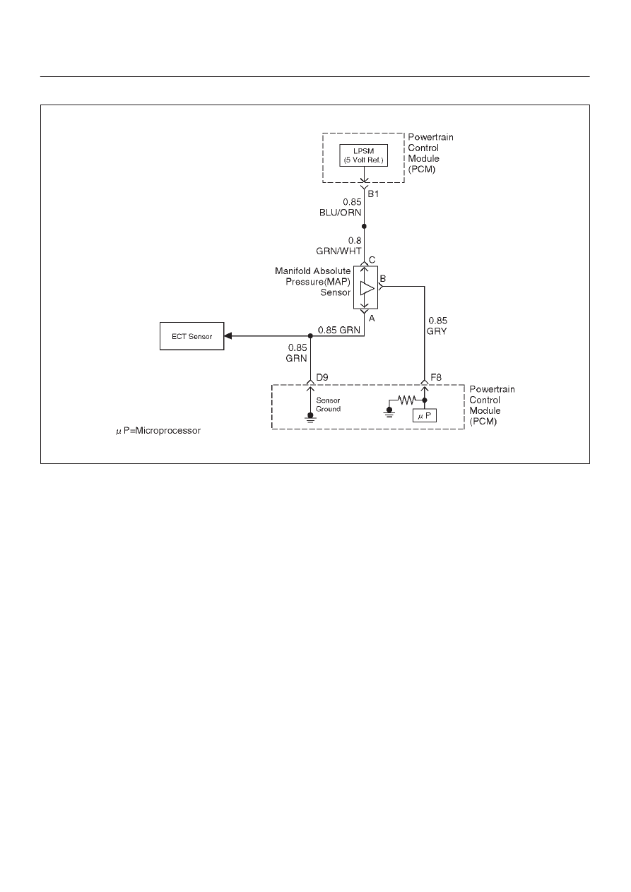
Circuit Description
The manifold absolute pressure (MAP) sensor responds
to changes in intake manifold pressure (vacuum). The
MAP sensor signal voltage to the powertrain control
module (PCM) varies from below 2 volts at idle (high
vacuum) to above 4 volts with the ignition “ON,” engine
not running or at wide-open throttle (low vacuum).
The MAP sensor is used to determine manifold pressure.
The PCM monitors the MAP signals for voltages outside
the normal range of the MAP sensor. If the PCM detects a
MAP signal voltage that is excessively low, DTC P0107
will be set.
Conditions for Setting the DTC
D
No TP sensor DTCs present.
D
Engine is running.
D
Throttle angle is above 1% if engine speed is less than
1000 RPM.
D
Throttle angle is above 2% if engine speed is above
1000 RPM.
D
The MAP sensor indicates manifold absolute pressure
at or below 11 kPa for a total of approximately 10
seconds over a 16-second period.
D
Ignition voltage more than 11 volts.
Action Taken When the DTC Sets
D
The PCM will illuminate the malfunction indicator lamp
(MIL) the first time the fault is detected.
D
The PCM will default to a BARO value of 79.3 kPa.
D
The PCM will store conditions which were present
when the DTC was set as Freeze Frame and in the
Failure Records data.
Conditions for Clearing the MIL/DTC
D
The PCM will turn the MIL “OFF” on the third
consecutive trip cycle during which the diagnostic has
been run and the fault condition is no longer present.
D
A history DTC P0107 will clear after 40 consecutive
warm-up cycles have occurred without a fault.
D
DTC P0107 can be cleared by using the Tech 2 “Clear
Info” function or by disconnecting the PCM battery
feed.
Diagnostic Aids
Check for the following conditions:
D
Check for intermittent codes.
D
The MAP sensor shares a ground with the Fuel Tank
Pressure Sensor, the ECT sensor, and the
Transmission Fluid Temperature sensor.
D
Poor connection at PCM – Inspect harness connectors
for backed-out terminals, improper mating, broken
locks, improperly formed or damaged terminals, and
poor terminal-to-wire connection.
D
Damaged harness – Inspect the wiring harness for
damage. If the harness appears to be OK, observe the
MAP display on the Tech 2 while moving connectors
and wiring harnesses related to the sensor. A change
in the display will indicate the location of the fault.
If DTC P0107 cannot be duplicated, the information
included in the Failure Records data can be useful in