Opel Frontera UE. Manual - part 928
6E2–98
6VD1 3.2L ENGINE DRIVEABILITY AND EMISSIONS
Diagnostic Trouble Code (DTC) P0101 MAF System Performance
D06RW057
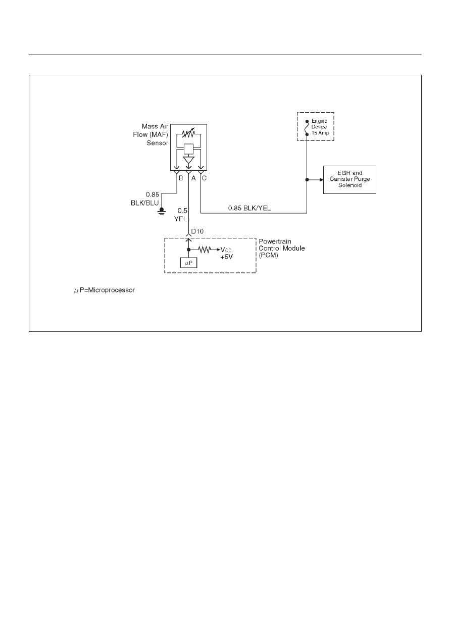
Circuit Description
The mass air flow (MAF) sensor measures the amount of
air which passes through it into the engine during a given
time. The powertrain control module (PCM) uses the
mass air flow information to monitor engine operating
conditions for fuel delivery calculations. A large quantity
of air entering the engine indicates an acceleration or high
load situation, while a small quantity or air indicates
deceleration or idle.
The MAF sensor produces a frequency signal which can
be monitored using a Tech 2. The frequency will vary
within a range of around 4 to 7 g/s at idle to around 25 to 40
g/s at maximum engine load. DTC P0101 will be set if the
signal from the MAF sensor does not match a predicted
value based on throttle position and engine RPM.
Conditions for Setting the DTC
D
The engine is running.
D
No TP sensor or MAP sensor DTCs are set.
D
The throttle is steady, TP angle doesn’t change by
more than 1%.
D
System voltage is between 11.5 volts and 16 volts.
D
Calculated air flow is between 25 g/second and 40
g/second.
D
Above conditions present for at least 1 second.
D
MAF signal frequency indicates an airflow significantly
higher or lower than a predicted value based on throttle
position and engine RPM for a total of 12.5 seconds
over a 25-second period of time.
Action Taken When the DTC Sets
D
The PCM will illuminate the malfunction indicator lamp
(MIL) after the second consecutive trip in which the
fault is detected.
D
The PCM calculates an airflow value based on idle air
control valve position, throttle position, RPM and
barometric pressure.
D
The PCM will store conditions which were present
when the DTC was set as Freeze Frame and in the
Failure Records data.
Conditions for Clearing the MIL/DTC
D
The PCM will turn the MIL “OFF” on the third
consecutive trip cycle during which the diagnostic has
been run and the fault condition is no longer present.
D
A history DTC P0101 will clear after 40 consecutive
warm-up cycles have occurred without a fault.
D
DTC P0101 can be cleared by using the Tech 2 “Clear
Info” function or by disconnecting the PCM battery
feed.
Diagnostic Aids
An intermittent may be caused by the following:
D
Poor connections.
D
Mis-routed harness.
D
Rubbed through wire insulation.
D
Broken wire inside the insulation.
Refer to Intermittents under service category Symptoms.
Any un-metered air may cause this DTC to set. Check for
the following: