Opel Frontera UE. Manual - part 921
6E2–70
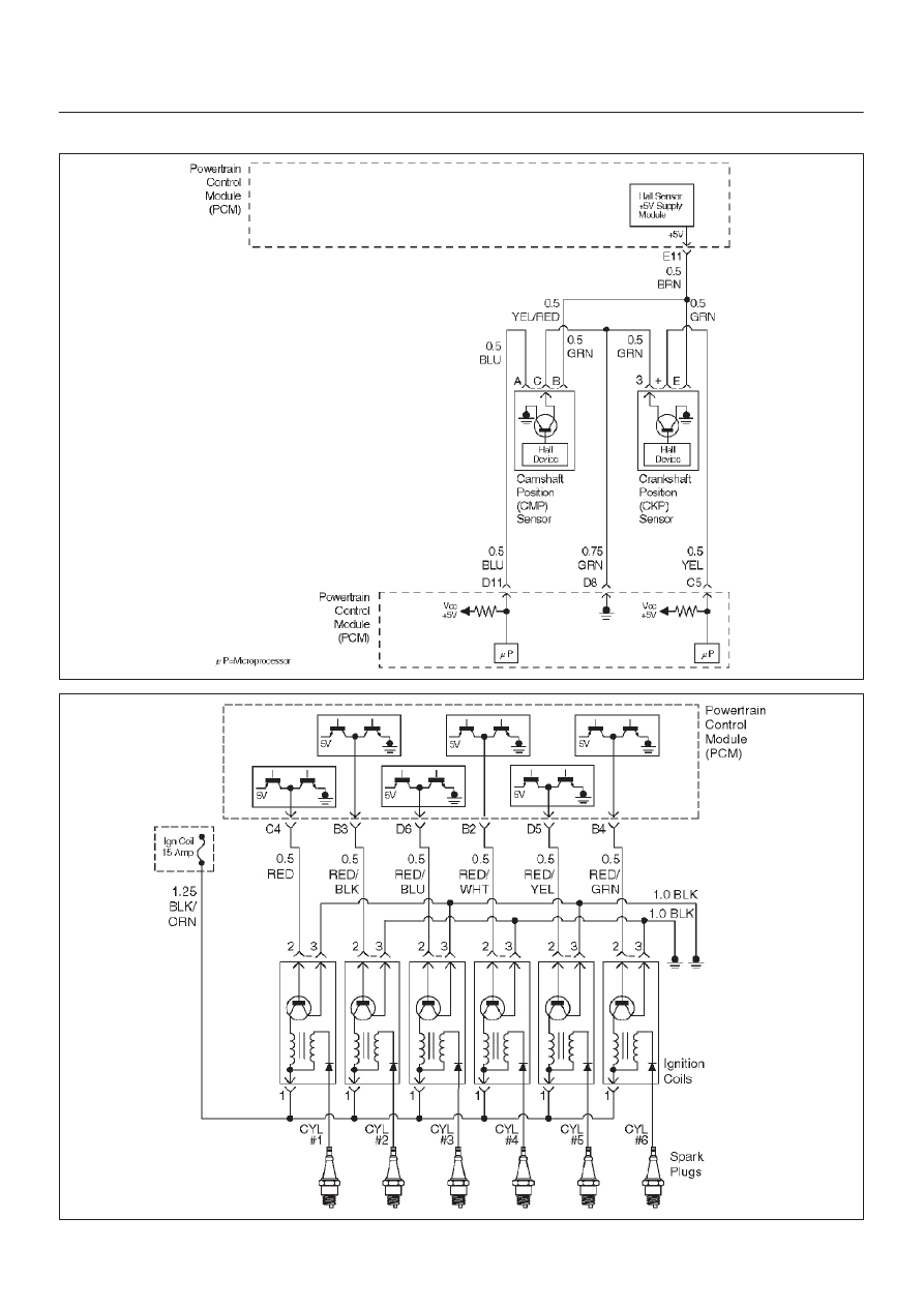
6VD1 3.2L ENGINE DRIVEABILITY AND EMISSIONS
Engine Cranks But Will Not Run
D06RX145
060RY00303
|
|
|
6E2–70 6VD1 3.2L ENGINE DRIVEABILITY AND EMISSIONS Engine Cranks But Will Not Run D06RX145 060RY00303 |