Opel Frontera UE. Manual - part 919
6E2–62
6VD1 3.2L ENGINE DRIVEABILITY AND EMISSIONS
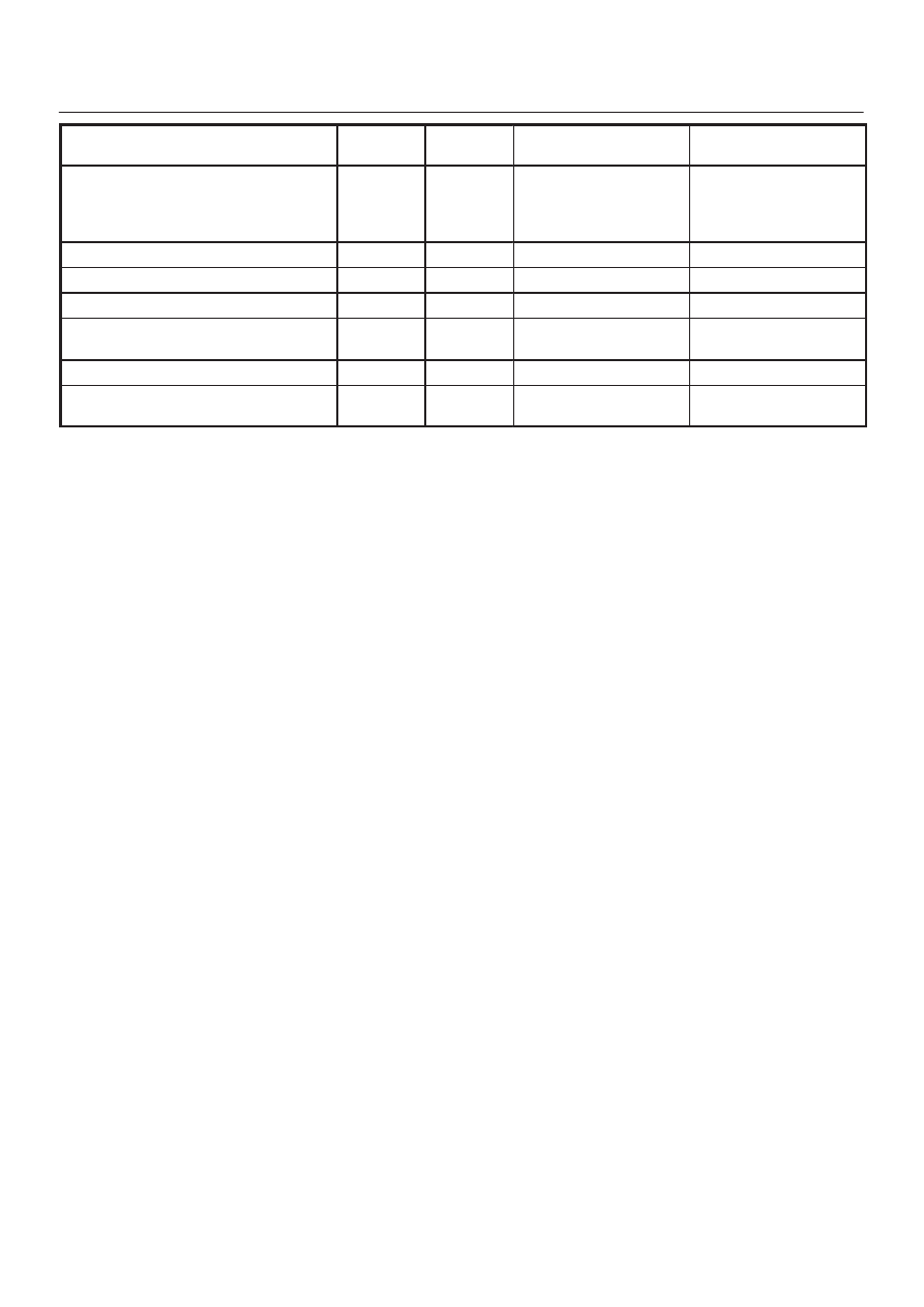
Tech 2 Parameter
Typical Data Values
(2500 RPM)
Typical Data Values
(IDLE)
Units
Displayed
Data List
Fuel system Status
Engine
Closed
Loop
/Open
Loop
Closed Loop
Closed Loop
Power Enrichment
Engine
Yes/No
No
No
Engine Load
Engine
%
2.0 – 5.5
8.0 – 16.0
Time From Start
Engine
_:_:_
_:_:_
_:_:_
Deceleration Fuel Cutoff
Engine
Inactive/A
ctive
Inactive
Inactive
Malfunction Indicator Lamp
Engine
On/Off
Off
Off
VIM solenoid (Variable Intake
Manifold)
Engine
On/Off
On
On