Opel Frontera UE. Manual - part 885
6A–89
ENGINE MECHANICAL (6VD1 3.2L)
Cylinder Block
Cylinder Block and Associated Parts
012RW010
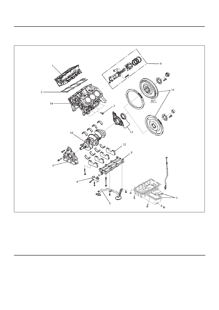
Legend
(1) Cylinder Head Assembly
(2) Cylinder Head Gasket
(3) Crankcase with Oil Pan
(4) Oil Pipe and O-Ring
(5) Oil Strainer and O-Ring
(6) Oil Pump Assembly
(7) Cylinder Block Side Bolts
(8) Oil Gallery
(9) Piston and Connecting Rod Assembly
(10) Flywheel
(11) Rear Oil Seal Retainer Assembly
(12) Main Bearing Cap
(13) Crankshaft
(14) Cylinder Block
Disassembly
1. Remove cylinder head assembly.
2. Remove cylinder head gasket.
3. Remove crankcase with oil pan.
4. Remove oil pipe and O-ring.
5. Remove oil strainer and O-ring.
6. Remove oil pump assembly.
7. Remove crankcase side bolts.
8. Remove oil gallery.
9. Remove piston and connecting rod assembly.
10. Remove flywheel.