Opel Frontera UE. Manual - part 883
6A–81
ENGINE MECHANICAL (6VD1 3.2L)
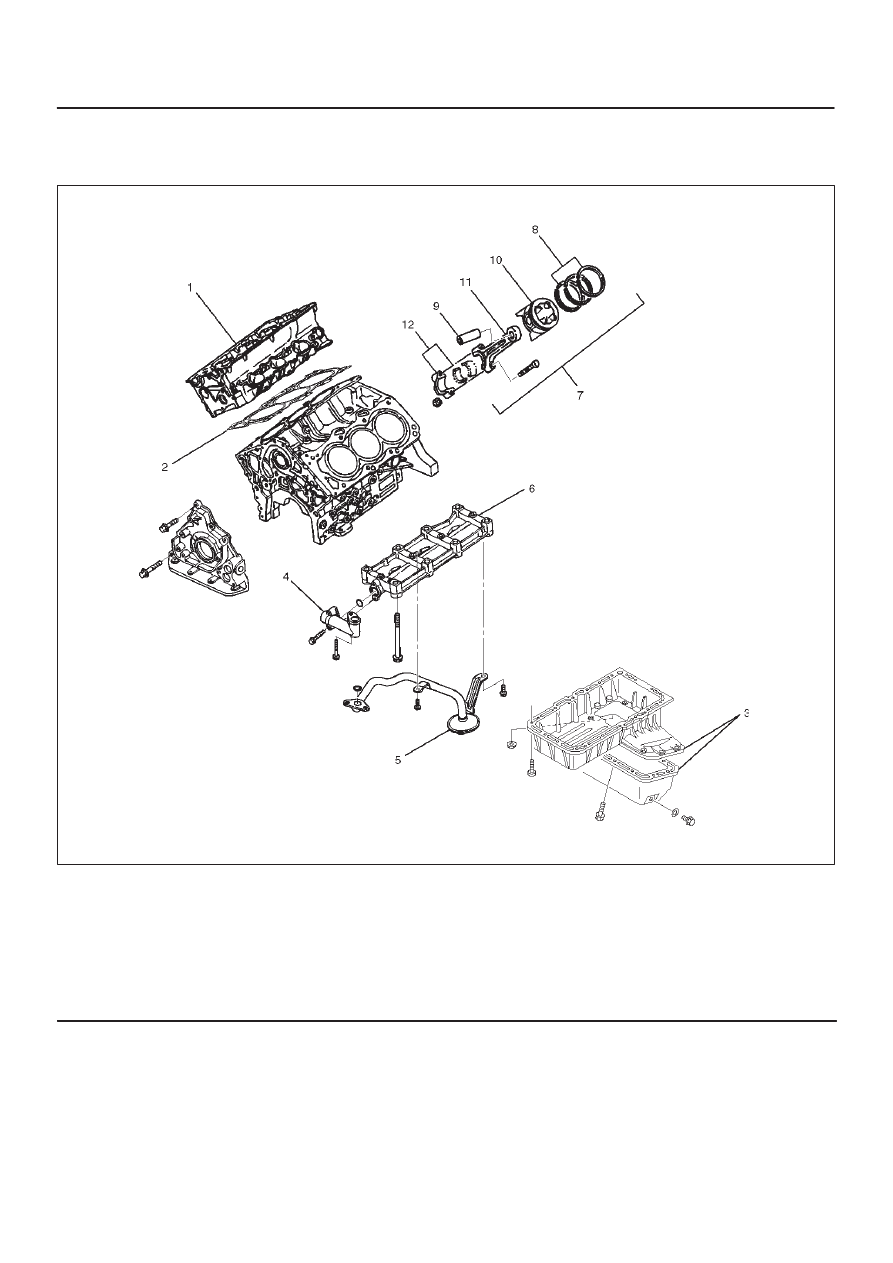
Piston and Connecting Rod
Piston, Connecting Rod and Associate Parts
015RW019
Legend
(1) Cylinder Head Assembly
(2) Cylinder Head Gasket
(3) Crankcase with Oil Pan
(4) Oil Pipe and O-Ring
(5) Oil Strainer and O-Ring
(6) Oil Gallery
(7) Piston and Connecting Rod Assembly
(8) Piston Ring
(9) Piston Pin
(10) Piston
(11) Connecting Rod
(12) Connecting Rod Cap
Disassembly
1. Remove cylinder head assembly (1). Refer to
“Cylinder Head Removal” in this manual.
2. Remove cylinder head gasket (2).
3. Remove crankcase with oil pan (3). Refer to“Oil Pan
and Crankcase” in this manual.
4. Remove oil pipe and O-ring (4).
5. Remove oil strainer and O-ring (5).
6. Remove oil gallery (6).
7. Remove connecting rod cap with connecting rod
lower bearing (12).
8. Remove piston and connecting rod assembly (7).
NOTE: Before removing piston and connecting rod
assembly, measure thrust clearance.