Opel Frontera UE. Manual - part 882
6A–77
ENGINE MECHANICAL (6VD1 3.2L)
Main
Bearing
Grade Mark
On Cylinder
Block
Main Bearing Bore
Diameter
mm (in)
Crank Shaft Main
Journal Diameter
mm (in)
Crankshaft
Bearing
Grade Mark
On
Crankshaft
Crankshaft
Bearing Size
Mark (collor
indicator)
Oil Clearance
(Reference)
mm (in)
1
68.994-69.000
63.918-63.925
(2.5165-2.5167)
2
Blue
1
(2.7163-2.7165)
63.926-63.933
(2.5168-2.5170)
1
Brown
2
68.987-68.993
63.918-63.925
(2.5165-2.5167)
2
Brown
0.019–0.043
2
(2.7160-2.7163)
63.926-63.933
(2.5168-2.5170)
1
Green
(0.0007–0.0017)
3
68.980-68.986
63.918-63.925
(2.5165-2.5167)
2
Green
3
(2.7157-2.7160)
63.926-63.933
(2.5168-2.5170)
1
Yellow
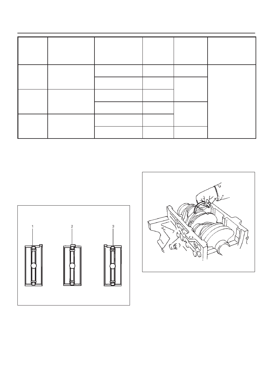
Reassembly
1. Crankshaft
D
Install the main bearings to the cylinder block and
the main bearing caps.
D
Be sure that they are positioned correctly.
D
Apply new engine oil to the upper and lower main
bearing faces.
NOTE: Do not apply engine oil to the main bearing back
faces.
015RS012
D
Carefully mount the crankshaft.
D
Apply engine oil to the thrust washer.
D
Assemble the thrust washer to the No.3 bearing
journal. The oil grooves must face the crankshaft.
015R100033
2. Rear oil seal
D
Remove the oil from the cylinder block and the
retainer mounting surface.
D
Apply sealant (TB–1207B or equivalent) to the
retainer mounting surface, following the pattern
shown in the illustration.
The retainer must be installed within 5 minutes
after sealant application befor the sealant hardens.