Opel Frontera UE. Manual - part 869
6A–25
ENGINE MECHANICAL (6VD1 3.2L)
Cylinder Head Cover RH
Removal
1. Disconnect the battery ground cable.
2. Remove the engine cover from the dowels on the
common chamber.
F06RW018
3. Disconnect the wires and bonding cables.
D
Exhaust Gas Recirculation (EGR) valve
D
Fuel injectors for right cylinder bank
D
Ignition coils for right cylinder bank
D
Bonding cable
D
Other parts as required
4. Remove the engine harness from the cylinder head
cover.
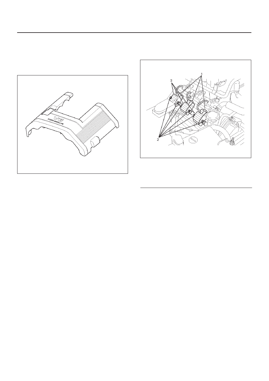
060RW001
Legend
(1) Ignition Coil Connectors
(2) Bolts
(3) Ignition Coil Assemblies
5. Remove the ignition coil assemblies from the right
cylinder bank.
6. Remove the cylinder head cover assembly.