Opel Frontera UE. Manual - part 858


  Index      Opel     Opel Frontera UE - service repair manual 1999-2001 year


Search            copyright infringement  


Content   ..  856  857  858  859   ..


Opel Frontera UE. Manual - part 858


6E1–315

X22SE 2.2L ENGINE DRIVEABILITY AND EMISSION

Spark Plug

Although worn or dirty spark plugs may give satisfactory
operation at idling speed, they frequently fail at higher
engine speeds. Faulty spark plugs may cause poor fuel
economy, power loss, loss of speed, hard starting and
generally poor engine performance. Follow the
scheduled maintenance service recommendations to
ensure satisfactory spark plug performance. Refer to
Maintenance and Lubrication.
Normal spark plug operation will result in brown to
grayish–tan deposits appearing on the insulator portion of
the spark plug. A small amount of red–brown, yellow, and
white powdery material may also be present on the
insulator tip around the center electrode. These deposits
are normal combustion by–products of fuels and
lubricating oils with additives. Some electrode wear will
also occur.
Carbon fouling of the spark plug is indicated by dry, black
carbon (soot) deposits on the portion of the spark plug in
the cylinder. Excessive idling and slow speeds under light
engine loads can keep the spark plug temperatures so
low that these deposits are not burned off. Very rich fuel
mixtures or poor ignition system output may also be the
cause.Refer to DTC P0172.
Oil fouling of the spark plug is indicated by wet oily
deposits on the portion of the spark plug in the cylinder,
usually with little electrode wear. This may be caused by
oil during break–in of new or newly overhauled engines.
Deposit fouling of the spark plug occurs when the normal
red–brown, yellow or white deposits of combustion
by–products become sufficient to cause misfiring. In
some cases, these deposits may melt and form a shiny
glaze on the insulator around the center electrode. If the
fouling is found in only one or two cylinders, valve stem
clearances or intake valve seals may be allowing excess
lubricating oil to enter the cylinder, particularly if the
deposits are heavier on the side of the spark plug facing
the intake valve.

TS23995

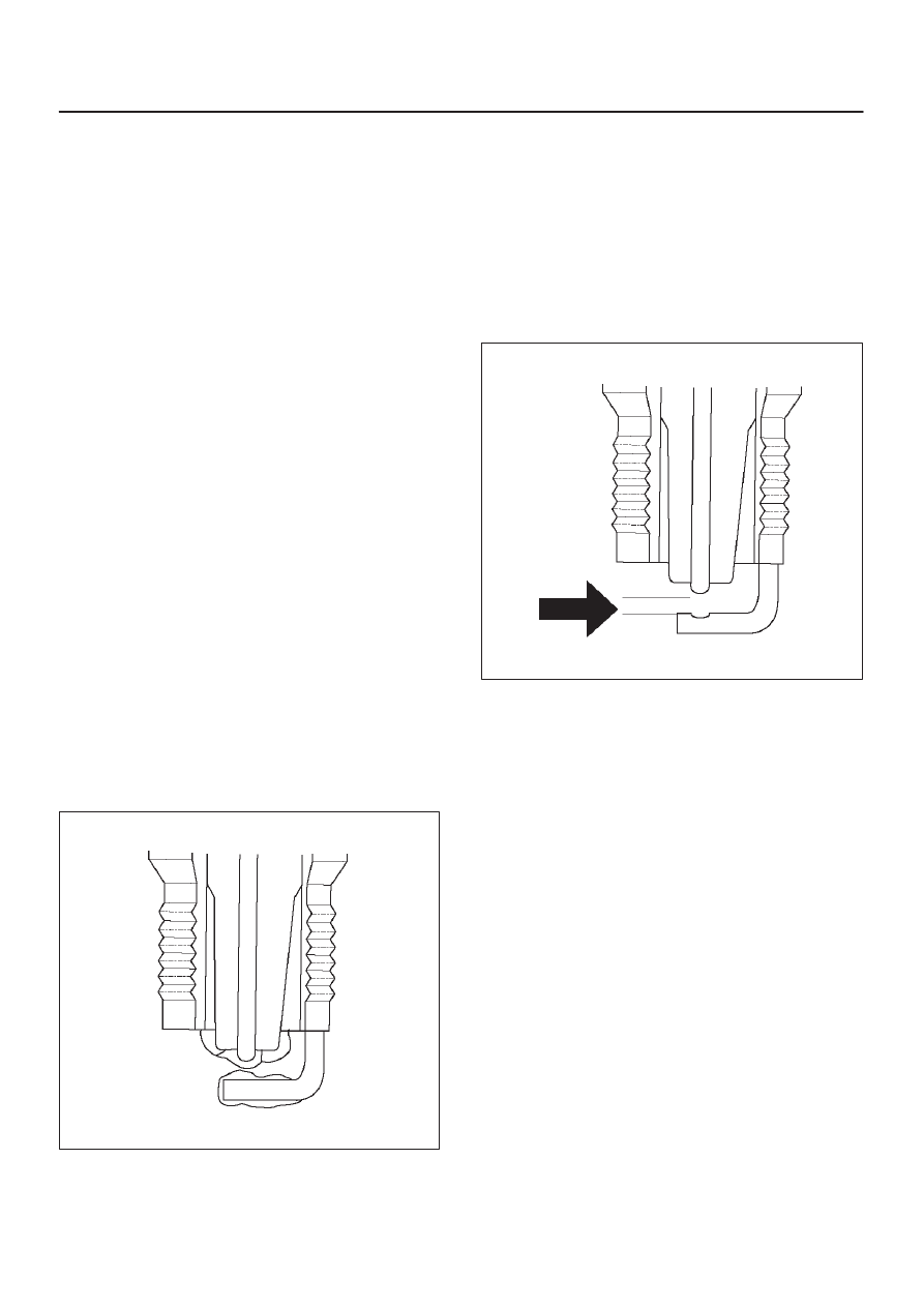
Excessive gap means that the air space between the
center and the side electrodes at the bottom of the spark
plug is too wide for consistent firing. This may be due to
improper gap adjustment or to excessive wear of the
electrode during use. A check of the gap size and
comparison to the gap specified for the vehicle in
Maintenance and Lubrication will tell if the gap is too wide.
A spark plug gap that is too small may cause an unstable
idle condition. Excessive gap wear can be an indication of
continuous operation at high speeds or with engine loads,
causing the spark to run too hot. Another possible cause
is an excessively lean fuel mixture.

TS23992

Low or high spark plug installation torque or improper
seating can result in the spark plug running too hot and
can cause excessive center electrode wear. The plug and
the cylinder head seats must be in good contact for proper
heat transfer and spark plug cooling. Dirty or damaged
threads in the head or on the spark plug can keep it from
seating even though the proper torque is applied. Once
spark plugs are properly seated, tighten them to the
torque shown in the Specifications Table. Low torque may
result in poor contact of the seats due to a loose spark
plug. Overtightening may cause the spark plug shell to be
stretched and will result in poor contact between the
seats. In extreme cases, exhaust blow–by and damage
beyond simple gap wear may occur.
Cracked or broken insulators may be the result of
improper installation, damage during spark plug
re–gapping, or heat shock to the insulator material. Upper
insulators can be broken when a poorly fitting tool is used
during installation or removal, when the spark plug is hit
from the outside, or is dropped on a hard surface. Cracks
in the upper insulator may be inside the shell and not
visible. Also, the breakage may not cause problems until
oil or moisture penetrates the crack later.

6E1–316

X22SE 2.2L ENGINE DRIVEABILITY AND EMISSION

TS23994

A broken or cracked lower insulator tip (around the center
electrode) may result from damage during re–gapping or
from ”heat shock” (spark plug suddenly operating too
hot).

TS23993

D

Damage during re–gapping can happen if the
gapping tool is pushed against the center electrode or
the insulator around it, causing the insulator to crack.
When re–gapping a spark plug, make the adjustment
by bending only the ground side terminal, keeping the
tool clear of other parts.

D

”Heat shock” breakage in the lower insulator tip
generally occurs during several engine operating
conditions (high speeds or heavy loading) and may be
caused by over–advanced timing or low grade fuels.
Heat shock refers to a rapid increase in the tip
temperature that causes the insulator material to
crack.

Spark plugs with less than the recommended amount of
service can sometimes be cleaned and re–gapped, then
returned to service. However, if there is any doubt about
the serviceability of a spark plug, replace it. Spark plugs
with cracked or broken insulators should always be
replaced.

A/C CLUTCH DIAGNOSIS

A/C Clutch Circuit Operation

A 12–volt signal is supplied to the A/C request input of the
ECM when the A/C is selected through the A/C control
switch.
The A/C compressor clutch relay is controlled through the
ECM. This allows the ECM to modify the idle air control
position prior to the A/C clutch engagement for better idle
quality. If the engine operating conditions are within their
specified calibrated acceptable ranges, the ECM will
enable the A/C compressor relay. This is done by
providing a ground path for the A/C relay coil within the
ECM. When the A/C compressor relay is enabled, battery
voltage is supplied to the compressor clutch coil.  The
ECM will enable the A/C compressor clutch whenever the
engine is running and the A/C has been requested. The
ECM will not enable the A/C compressor clutch if any of
the following conditions are met:

D

The engine speed is greater than 6315 RPM.

D

The ECT is greater than 119

°

C (246

°

F).

D

The throttle is more than 80% open.

A/C Clutch Circuit Purpose

The A/C compressor operation is controlled by the engine
control module (ECM) for the following reasons:

D

It improves idle quality during compressor clutch
engagement.

D

It improves wide open throttle (WOT) performance.

D

It provides A/C compressor protection from operation
with incorrect refrigerant pressures.

The A/C electrical system consists of the following
components:

1. The A/C control switch.
2. The A/C refrigerant pressure switches.
3. The A/C compressor clutch.
4. The A/C compressor clutch relay.
5. The ECM.

A/C Request Signal

This signal tells the ECM when the A/C mode is selected
at the A/C control switch. The ECM uses this input to
adjust the idle speed before turning on the A/C clutch. The
A/C compressor will be inoperative if this signal is not
available to the ECM.
For A/C wiring diagrams and diagnosis for the A/C
electrical system, refer to A/C Clutch Circuit Diagnosis.

GENERAL DESCRIPTION —
EVAPORATIVE EMISSION (EVAP)
SYSTEM

EVAP Emission Control System Purpose

The basic evaporative emission (EVAP) control system
used on all vehicles is the charcoal canister storage
method.  Gasoline vapors from the fuel tank flow into the
canister through the inlet labeled ”TANK.” These vapors
are absorbed into the activated carbon (charcoal) storage

6E1–317

X22SE 2.2L ENGINE DRIVEABILITY AND EMISSION

device (canister) in order to hold the vapors when the
vehicle is not operating. The canister is purged by ECM
control when the engine coolant temperature is over 60

°

C

(140

°

F), the IAT reading is over 10

°

C (50

°

F), and the

engine has been running. Air is drawn canister through
the air inlet grid. The air mixes with the vapor and the
mixture is drawn into the intake manifold.

EVAP Emission Control System Operation

The EVAP canister purge is controlled by a solenoid valve
that allows the manifold vacuum to purge the canister.
The Engine Control Module (ECM) supplies a ground to
energize the solenoid valve (purge on).  The EVAP purge
solenoid control is pulse–width modulated (PWM) (turned
on and off several times a second). The duty cycle (pulse
width) is determined by engine operating conditions
including load, throttle position, coolant temperature and
ambient temperature. The duty cycle is calculated by the
ECM. The output is commanded when the appropriate
conditions have been met. These conditions are:

D

The engine is fully warmed up.

D

The engine has been running for a specified time.

D

The IAT reading is above 10

°

C (50

°

F).

Poor idle, stalling and Poor driveability can be caused by:

D

A malfunctioning purge solenoid.

D

A damaged canister.

D

Hoses that are split, cracked, or not connected
properly.

GENERAL DESCRIPTION —
EXHAUST GAS RECIRCULATION
(EGR) SYSTEM

EGR Purpose

The exhaust gas recirculation (EGR) system is used to
reduce emission levels of oxides of nitrogen (NOx). NOx
emission levels are caused by a high combustion
temperature. The EGR system lowers the NOx emission
levels by decreasing the combustion temperature.

Linear EGR Valve

The main element of the system is the linear EGR valve.
The EGR valve feeds small amounts of exhaust gas back
into the combustion chamber. The fuel/air mixture will be
diluted and combustion temperatures reduced.

Linear EGR Control

The ECM monitors the EGR actual position and adjusts
the pintle position accordingly. The ECM uses information
from the following sensors to control the pintle position:

D

Engine coolant temperature (ECT) sensor.

D

Throttle position (TP) sensor.

Linear EGR Valve Operation And Results
Of Incorrect Operation

The linear EGR valve is designed to accurately supply
EGR to the engine independent of intake manifold

vacuum. The valve controls EGR flow from the exhaust to
the intake manifold through an orifice with a
ECM–controlled pintle. During operation, the ECM
controls pintle position by monitoring the pintle position
feedback signal. The feedback signal can be monitored
with a Tech 2 as ”Actual EGR Pos.” ”Actual EGR Pos.”
should always be near the commanded EGR position
(”Desired EGR Pos.”). The ECM also tests for EGR flow.
If incorrect flow is detected, DTC P0401 will set. If DTC
P0401 is set, refer to the DTC charts.
The linear EGR valve is usually activated under the
following conditions:

D

Warm engine operation.

D

Above–idle speed.

Too much EGR flow at idle, cruise or cold operation may
cause any of the following conditions to occur:

D

Engine stalls after a cold start.

D

Engine stalls at idle after deceleration.

D

Vehicle surges during cruise.

D

Rough idle.

D

DTC P0300 (misfire detected).

Too little or no EGR flow may allow combustion
temperatures to get too high. This could cause:

D

Spark knock (detonation).

D

Engine overheating.

D

Emission test failure.

D

DTC P0401 (EGR Flow Insufficient detected).

D

Poor fuel economy.

0017

EGR Pintle Position Sensor

The ECM monitors the EGR valve pintle position input to
ensure that the valve responds properly to commands
from the ECM and to detect a fault if the pintle position
sensor and control circuits are open or shorted. If the
ECM detects a pintle position signal voltage outside the
normal range of the pintle position sensor, or a signal
voltage that is not within a tolerance considered

6E1–318

X22SE 2.2L ENGINE DRIVEABILITY AND EMISSION

acceptable for proper EGR system operation, the ECM
will set DTC P0404.

GENERAL DESCRIPTION —
POSITIVE CRANKCASE
VENTILATION (PCV) SYSTEM

Crankcase Ventilation System Purpose

The crankcase ventilation system is used to consume
crankcase vapors in the combustion process instead of
venting them to the atmosphere. Fresh air from the
throttle body is supplied to the crankcase and mixed with
blow–by gases. This mixture is then passed through the
positive crankcase ventilation (PCV) port into the intake
manifold.
While the engine is running, exhaust gases and small
amounts of the fuel/air mixture escape past the piston
rings and enter the crankcase. These gases are mixed
with clean air entering through a tube from the air intake
duct.

028RX003

During normal, part–throttle operation, the system is
designed to allow crankcase gases to flow through the
PCV valve into the throttle body to be consumed by
normal combustion.
A plugged valve or PCV hose may cause the following
conditions:

D

Rough idle.

D

Stalling or slow idle speed.

D

Oil leaks.

D

Sludge in the engine.

A leaking PCV hose would cause:

D

Rough idle.

D

Stalling.

D

High idle speed.


Content   ..  856  857  858  859   ..