Opel Frontera UE. Manual - part 849


  Index      Opel     Opel Frontera UE - service repair manual 1999-2001 year


Search            copyright infringement  


Content   ..  847  848  849  850   ..


Opel Frontera UE. Manual - part 849


6E1–279

X22SE 2.2L ENGINE DRIVEABILITY AND EMISSION

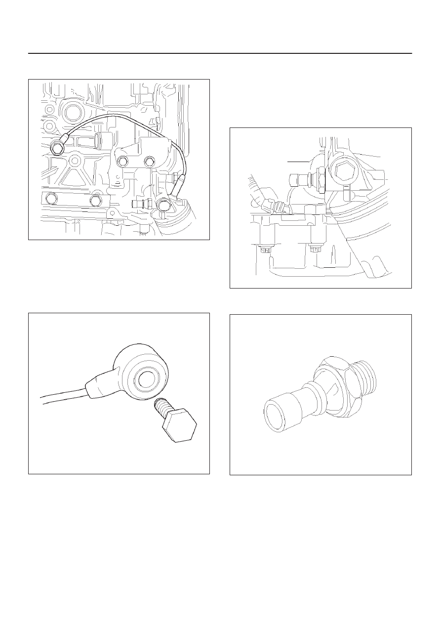
3. Unscrew retaining bolt from Knock Sensor located

passenger side of engine block just front of starter.

014RX028

4. Remove Knock Sensor with retaining bolt.

Installation Procedure

1. Install Knock Sensor with retaining bolt.
2. Connect pig tail electrical connector.
3. Connect battery negative cable.

014RX029

Oil Pressure Switch

Removal Procedure

1. Disconnect battery negative cable.
2. Disconnect electrical connector at Oil Pressure

Switch.

014RX030

3. Unscrew Oil Pressure Switch from Oil Filter Mounting

Housing.

014RX031

6E1–280

X22SE 2.2L ENGINE DRIVEABILITY AND EMISSION

Installation Procedure

1. Install Oil Pressure Switch into Oil Filter Mounting

Housing and tighten.

2. Connect electrical connector.
3. Connect battery negative cable.

014RX028

FUEL METERING SYSTEM  Ac-

celerator Cable Assembly

Removal Procedure

1. Loosen the adjusting nut on the cable bracket

mounting on the throttle body.

2. Remove the cable clip from holding bracket.

014RX026

3. Remove accelerator control cable (on the throttle

valve end).

101RW006

4. Remove the accelerator control cable (on the

accelerator pedal end).

5. Remove the grommet.
6. Remove the accelerator control cable.

Inspection Procedure

Check the following items, and replace the control cable if
any abnormality is found:

D

The control cable should move smoothly.

D

The control cable should not be bent or kinked.

D

The control cable should be free of damage and
corrosion.

014RX032

6E1–281

X22SE 2.2L ENGINE DRIVEABILITY AND EMISSION

Installation Procedure

1. Install the accelerator control cable.
2. Install the grommet.
3. Install the accelerator control cable on the accelerator

pedal.

014RX032

4. Install the accelerator control cable on the throttle

valve.

101RW006

5. Install the cable clip to the holding bracket.

6. Adjust the accelerator cable. Refer to Accelerator

Cable Adjustment Section. 

014RX026

Accelerator Cable  Adjustment

Adjustment Procedure

1. Loosen the adjusting nut.
2. Loosen the jam nut.
3. Pull the outer cable while fully closing the throttle

valve.

4. Tighten the adjusting nut.
5. Tighten the jam nut.
6. Loosen the adjusting nut by three turns.
7. Tighten the jam nut again.
8. Manually operate valve.

IMPORTANT:

 The valve lever must return up to the

stopper screw.  If the valve lever does not reach the
stopper screw, repeat the procedure again from Step 1.

014RX026

6E1–282

X22SE 2.2L ENGINE DRIVEABILITY AND EMISSION

Accelerator Pedal Replacement

Removal Procedure

1. Disconnect the accelerator pedal control cable from

the acceleratorpedal assembly.

2. Remove the two screws retaining the accelerator

pedal to the bulkhead.

3. Remove the accelerator pedal from the bulkhead.

014RX033

Installation Procedure

1. Install the accelerator pedal assembly to the

bulkhead with two screws.

2. Connect the accelerator control cable to the

accelerator pedal assembly.

3. Adjust accelerator cable if necessary. Refer to

Accelerator Cable Adjustment Section. 

014RX034

Fuel Filler Cap

Fuel Filler Cap

The Fuel filter cap includes a vacuum valve and a
pressure valve. If high vacuum or pressure occurs in the
fuel tank, each valve works to adjust the pressure in order
to prevent damage to the tank at the EGR valve.

Inspection Procedure

NOTE: Replace the fuel filler cap with the same typeof
filler cap that was originally installed on the vehicle.

D

Check the seal ring in the filler cap for any abnormality
and for seal condition.

D

Replace the filler cap if any abnormality is found.

TS23767

Fuel Filter

Removal Procedure

1. Disconnect the negative battery cable.


Content   ..  847  848  849  850   ..